
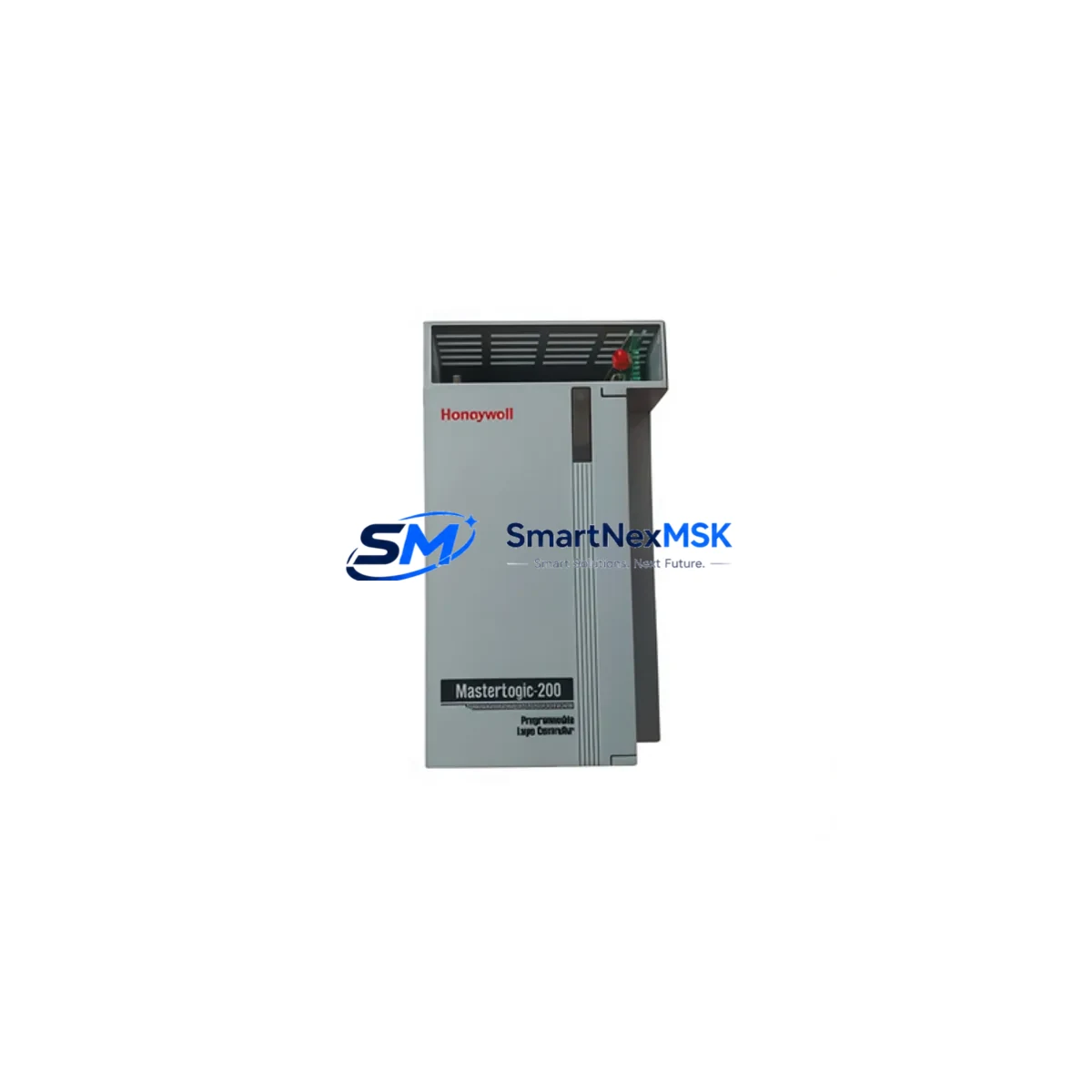
Honeywell 2MLR-DC42 Spare for TDC3000 Automation: Spare Replacement & Downtime Risk Control
The Honeywell 2MLR-DC42 is a DC power supply module designed for use within the TDC3000 Distributed Control System (DCS) platform — one of the most widely deployed process automation architectures in refining, petrochemical, and continuous manufacturing environments. As a maintenance-ready spare, the 2MLR-DC42 plays a critical role in sustaining power integrity across the TDC3000 control cabinet, ensuring that field I/O modules, communication cards, and controller nodes receive stable, regulated DC voltage without interruption.
For maintenance engineers managing aging TDC3000 installations, sourcing a verified original 2MLR-DC42 replacement is often the difference between a two-hour planned swap and a multi-day unplanned outage. This listing provides an original-specification 2MLR-DC42 unit, pre-tested prior to shipment, backed by a 12-month warranty, and available for fast dispatch to minimize your site downtime exposure.
Spare Maintenance Table
| Parameter | Specification / Detail |
|---|---|
| Part Number / SKU | 2MLR-DC42 |
| Brand | Honeywell |
| Series / Platform | TDC3000 DCS |
| Module Type | DC Power Supply Module |
| Output Voltage | +5 VDC / +24 VDC (regulated, per TDC3000 backplane spec) |
| Input Voltage Range | 85–264 VAC, 47–63 Hz (universal input) |
| Compatibility | Honeywell TDC3000 LCN / UCN / HPM / AM / NIM cabinets |
| Installation | Direct module slot replacement; no re-wiring required for like-for-like swap |
| Application Environment | Industrial control room, DCS cabinet, process automation panel |
| Operating Temperature | 0°C to +60°C (standard industrial range) |
| Maintenance Recommendation | Inspect every 12–18 months; replace proactively at first sign of output ripple or thermal alarm |
| Origin | USA (Original Honeywell manufacture) |
| Pre-Shipment Testing | Yes — functional output verification before dispatch |
| Warranty | 12 Months |
| Lead Time | In stock — same or next business day dispatch available |
Maintenance Planning for Continuous Operation
When a 2MLR-DC42 power supply module is flagged for replacement during a scheduled outage or emergency fault isolation, experienced maintenance engineers know that the power module is rarely the only component that warrants attention. A systematic cabinet inspection at the time of replacement significantly reduces the risk of repeat failures and secondary faults.
Begin by verifying the integrity of the TDC3000 backplane bus connectors — oxidized or loose backplane contacts are a common root cause of intermittent power faults that are incorrectly attributed to the supply module itself. Next, inspect the Honeywell PM/APM (Process Manager / Advanced Process Manager) controller cards seated in the same cabinet; a degraded power rail can cause latent damage to controller logic that only manifests after the supply is replaced.
Check the Honeywell NIM (Network Interface Module) and HG (Highway Gateway) communication cards for any fault LEDs or communication timeout alarms — these modules are sensitive to supply voltage transients and may require re-initialization after a power module swap. If the cabinet includes a Honeywell AM (Application Module), verify its power draw is within the rated capacity of the replacement 2MLR-DC42 to avoid overload conditions.
On the field wiring side, inspect the terminal blocks and marshalling panels connected to the I/O subsystem. Loose terminations or corroded field wiring can introduce ground loops that stress the DC supply. If the system uses Honeywell HPM (High-Performance Process Manager) I/O link cards, confirm that the I/O link cable integrity is sound — a degraded cable can cause the HPM to draw excess current during re-scan cycles.
For sites running signal isolators or loop-powered transmitters on the same 24 VDC bus, verify that the total loop current budget remains within the 2MLR-DC42’s rated output capacity after replacement. It is also advisable to inspect any 24 VDC fuse blocks or miniature circuit breakers in the distribution panel — a nuisance trip on a field circuit fuse is often the first symptom of a weakening power supply that has been operating in a degraded state.
Finally, if the TDC3000 cabinet includes a redundant power supply pair, confirm that the standby unit (often a second 2MLR-DC42 or equivalent) is functional and that the automatic changeover relay is operating correctly. A failed redundancy relay can leave the system running on a single supply without operator awareness, negating the protection that the redundant architecture was designed to provide.
Site Replacement Workflow
Step 1 — Pre-Replacement Verification: Confirm the fault is isolated to the 2MLR-DC42 by checking the TDC3000 system console for power fault alarms and measuring output voltage at the backplane test points. Document the current system state and notify the control room operator before proceeding.
Step 2 — Safe Isolation: If the cabinet has a redundant power supply, initiate a controlled switchover to the standby unit before removing the faulty module. For single-supply configurations, coordinate with operations for a planned process hold or safe state before de-energizing the cabinet section.
Step 3 — Module Removal and Inspection: Remove the 2MLR-DC42 by releasing the module locking mechanism and sliding it clear of the backplane. Inspect the backplane connector pins for damage, oxidation, or debris. Clean with appropriate contact cleaner if required before installing the replacement unit.
Step 4 — Replacement Installation: Insert the new 2MLR-DC42 into the module slot, ensuring full backplane engagement. The module is a direct like-for-like replacement — no jumper changes, DIP switch settings, or firmware configuration are required for standard TDC3000 installations.
Step 5 — Post-Installation Verification: Restore power and monitor the TDC3000 system console for alarm clearance. Verify output voltage at the backplane test points. Confirm that all controller, I/O, and communication modules in the cabinet have returned to normal operating status. Log the replacement in the site maintenance record with the new module serial number and installation date.
This workflow supports a target replacement time of under 60 minutes for a trained maintenance technician, minimizing process downtime and reducing the risk of secondary faults caused by rushed or incomplete installation procedures.
Spare Parts Support FAQ
Q1: Is this 2MLR-DC42 an original Honeywell module or a third-party equivalent?
This is an original Honeywell 2MLR-DC42 module, not a third-party reproduction or remanufactured substitute. Each unit is sourced from verified supply channels and undergoes functional output testing prior to shipment to confirm it meets original Honeywell specifications.
Q2: How do I confirm compatibility with my specific TDC3000 cabinet configuration?
The 2MLR-DC42 is compatible with standard TDC3000 LCN, UCN, HPM, AM, and NIM cabinet configurations that use the DC42 power supply slot. If you are unsure of your cabinet revision or have a non-standard configuration, please contact us with your cabinet model number and we will confirm compatibility before shipment.
Q3: What does the 12-month warranty cover, and what is the claims process?
The 12-month warranty covers manufacturing defects and functional failures under normal operating conditions. It does not cover damage caused by incorrect installation, overvoltage events, or physical mishandling. To initiate a warranty claim, contact our support team with the order number, fault description, and site installation date. Replacement or repair will be arranged within 5 business days of claim approval.
Q4: Can I order multiple units for long-term spare parts inventory?
Yes. We recommend holding a minimum of one spare 2MLR-DC42 per TDC3000 cabinet as part of a proactive spare parts strategy, particularly for sites where the TDC3000 system is approaching end-of-support lifecycle. Volume pricing is available for orders of 3 or more units. Contact us directly to discuss long-term supply agreements and consignment stock arrangements.
© 2026 SMARTNEXMSK. All rights reserved.
Original Source: https://smartnexmsk.com
Contact: [email protected] | +86 18259474341



