
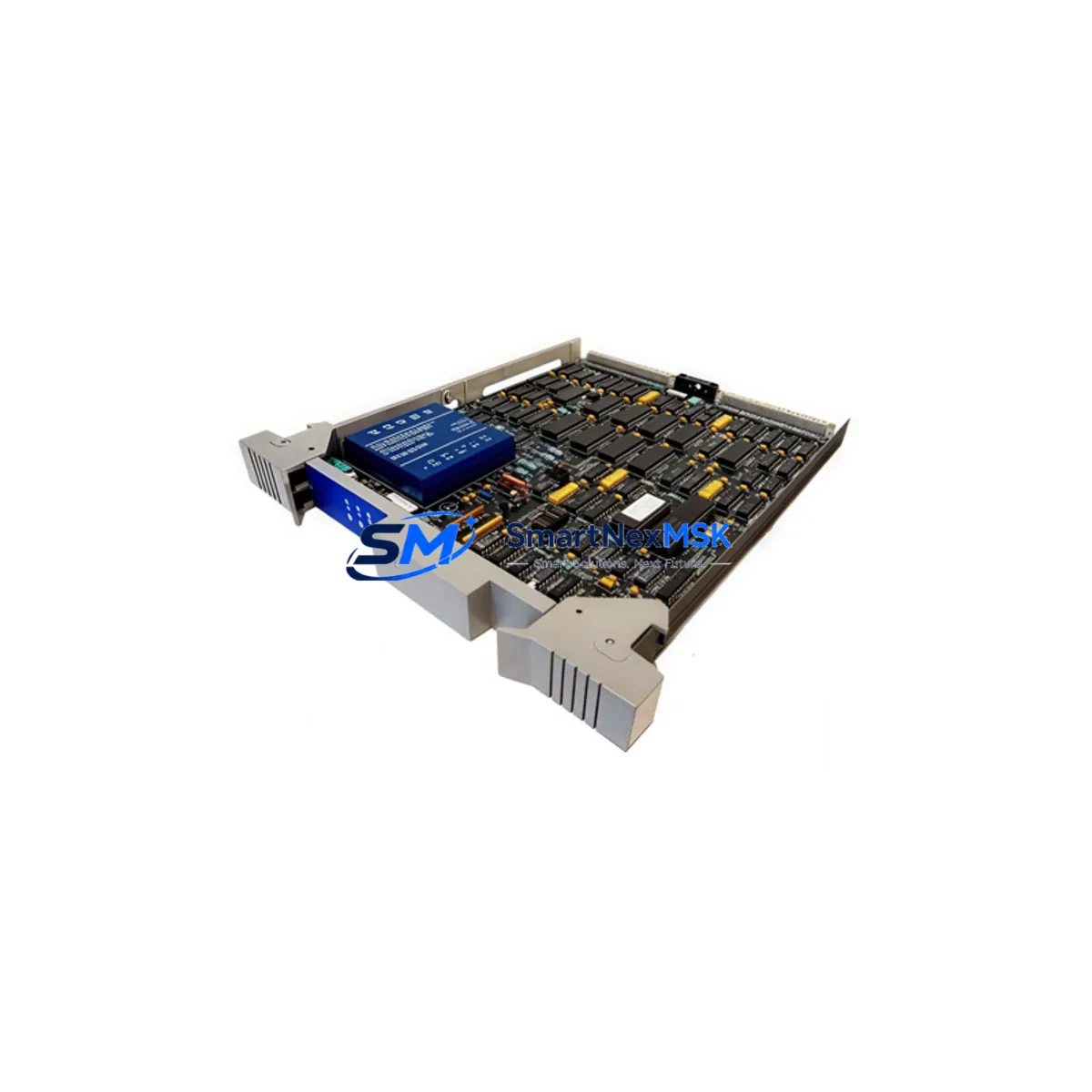
Honeywell 51303970-500 Maintenance-Ready Spare TDC 3000: Spare Replacement & Industrial Downtime Risk Control
The Honeywell 51303970-500 is an original PC Board module designed for the TDC 3000 Distributed Control System (DCS) platform — one of the most widely deployed process automation architectures in refining, petrochemical, power generation, and continuous manufacturing environments. As aging TDC 3000 systems remain in active service across global facilities, maintaining a verified stock of critical spare boards such as the 51303970-500 is essential for sustaining process continuity, reducing mean time to repair (MTTR), and protecting against unplanned production shutdowns.
This board is sourced as an original Honeywell component, fully tested prior to shipment, and backed by a 12-month warranty. Each unit undergoes functional verification to confirm electrical integrity and compatibility with TDC 3000 rack and backplane configurations before dispatch. Whether you are managing a planned turnaround, responding to an emergency fault, or building a strategic spare parts inventory, the 51303970-500 is a direct-fit replacement that eliminates the risk of compatibility mismatches and extended lead times associated with sourcing obsolete DCS components.
Spare Maintenance Table
| Parameter | Specification / Detail |
|---|---|
| Part Number / SKU | 51303970-500 |
| Brand | Honeywell |
| Series / Platform | TDC 3000 DCS |
| Module Type | PC Board / Printed Circuit Board Assembly |
| Compatibility | Honeywell TDC 3000 control cabinets and rack systems; compatible with standard TDC 3000 backplane configurations |
| Origin | USA (Original Honeywell manufacture) |
| Installation | Direct board-level replacement; observe ESD precautions; verify slot assignment per system documentation |
| Application Environment | Industrial process control; refining, petrochemical, power, continuous manufacturing |
| Pre-shipment Testing | Functional electrical verification performed on every unit |
| Warranty | 12 Months from date of shipment |
| Condition | Original spare — new or refurbished to OEM specification |
| Lead Time | In-stock units ship within 1–3 business days |
Maintenance Planning for Continuous Operation
When a TDC 3000 system fault is traced to the 51303970-500 board, experienced maintenance engineers know that a board-level failure rarely occurs in isolation. A thorough site inspection should accompany any board replacement to prevent repeat failures and confirm system-wide integrity.
Begin by inspecting the TDC 3000 power supply modules (such as the 51401288-100 or equivalent power conditioner boards) that feed the affected rack. Voltage irregularities or ripple on the DC bus are a common root cause of premature board failure and must be ruled out before installing a replacement. Simultaneously, check the backplane connectors and card cage for oxidation, bent pins, or mechanical damage — a compromised backplane will degrade the replacement board as quickly as the original.
Review the I/O termination assemblies and field wiring connected to the affected loop. Loose terminations, corroded field terminals, or miswired signal cables can introduce transient voltages that stress board components. If the system uses signal isolators or signal conditioners between field instruments and the DCS I/O, verify that these are functioning within specification — a failed isolator can inject noise or overvoltage into the board input circuits.
For systems with communication modules (such as Honeywell’s LCN or UCN network interface cards), confirm that network traffic and cable integrity are nominal. Communication faults can manifest as board-level alarms that are misdiagnosed as hardware failures. Similarly, inspect any relay output modules or discrete output boards in the same cabinet section, as inductive load switching can generate voltage spikes that propagate through shared power rails.
If the facility operates Honeywell HMI workstations or operator consoles connected to the TDC 3000 network, verify that the console software is correctly configured to recognize the replacement board after installation. Some TDC 3000 configurations require a database download or point re-assignment following a board swap. Coordinate with your DCS engineer to confirm the configuration management procedure before returning the loop to service.
Finally, review the fuse and circuit protection inventory for the affected cabinet. Blown fuses or tripped thermal protectors are often the first indicator of an overcurrent event that damaged the original board. Replacing fuses with the correct rated components — and not upsizing — is a critical step in protecting the new spare. Maintaining a cabinet-level spare kit that includes the 51303970-500 alongside power boards, I/O modules, communication cards, and terminal block assemblies is the most effective strategy for minimizing future downtime on aging TDC 3000 installations.
Site Replacement Workflow
Step 1 — Fault Isolation: Use the TDC 3000 system diagnostics to confirm the 51303970-500 board as the fault source. Document the slot address, loop assignments, and any active alarms before proceeding.
Step 2 — Safe Isolation: Follow your facility’s lockout/tagout (LOTO) procedure for the affected cabinet section. Discharge any residual voltage on the rack bus before handling the board. Use an ESD wrist strap and anti-static mat throughout the replacement procedure.
Step 3 — Board Removal: Carefully extract the faulty 51303970-500 from its slot. Inspect the backplane connector and card guides for damage. Retain the faulty board for failure analysis if required by your maintenance management system.
Step 4 — Replacement Installation: Verify that the replacement board’s revision level and firmware (if applicable) are compatible with your system configuration. Seat the board firmly into the slot and confirm the locking mechanism is engaged.
Step 5 — System Restoration: Restore power to the rack section and monitor the system diagnostic display for fault clearance. Perform a loop check on all I/O points associated with the replaced board. Confirm that all process values are reading correctly before returning the loop to automatic control.
Step 6 — Documentation: Record the replacement in your CMMS (Computerized Maintenance Management System), including the date, technician, board serial number, and post-replacement test results. Update your spare parts inventory to trigger a replenishment order for the consumed 51303970-500 unit.
Spare Parts Support FAQ
Q1: Is the 51303970-500 a direct drop-in replacement for all TDC 3000 configurations?
The 51303970-500 is designed for Honeywell TDC 3000 systems and is compatible with standard rack and backplane configurations within that platform. However, TDC 3000 installations vary by revision and site-specific engineering. We recommend confirming the board revision level and any firmware requirements against your system documentation before installation. Our technical team can assist with compatibility verification prior to shipment.
Q2: What testing is performed before shipment?
Every 51303970-500 unit undergoes functional electrical testing prior to dispatch. This includes verification of board power-up behavior, signal path integrity, and connector condition. Units that do not pass testing are not shipped. A test report can be provided upon request for critical applications.
Q3: How should I manage long-term spare parts inventory for TDC 3000 systems?
For facilities operating TDC 3000 systems beyond their original design life, we recommend maintaining a minimum of one spare 51303970-500 board per critical process unit, alongside spares for power supply modules, I/O boards, and communication cards. A structured spare parts audit every 12–24 months helps identify boards approaching end-of-life before they cause unplanned outages. We offer long-term supply agreements for customers requiring guaranteed stock availability.
Q4: What does the 12-month warranty cover?
The 12-month warranty covers manufacturing defects and functional failures under normal operating conditions. It does not cover damage resulting from incorrect installation, overvoltage events, physical mishandling, or use outside the specified environmental parameters. Warranty claims are processed promptly — contact our support team with the order reference and a description of the fault, and we will arrange a replacement or repair at no additional cost.
© 2026 SMARTNEXMSK. All rights reserved.
Original Source: https://smartnexmsk.com
Contact: [email protected] | +86 18259474341



