
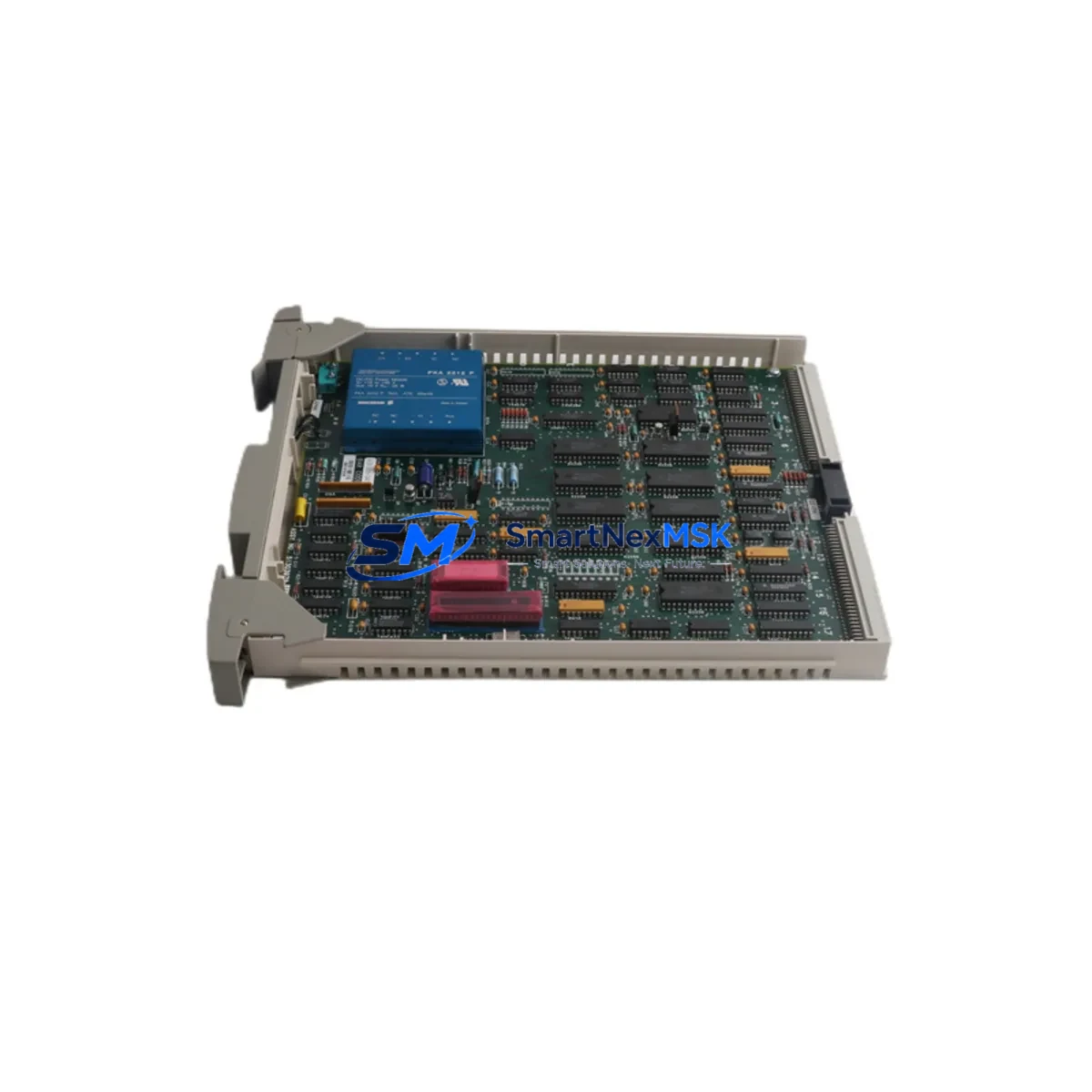
Honeywell 51303979-550 Retrofit-Ready Control Module for TDC 3000 Control Systems
The Honeywell 51303979-550 is a proven DCS control module engineered for seamless integration into legacy TDC 3000 distributed control architectures. As aging TDC 3000 installations approach end-of-support milestones, plant engineers and maintenance teams increasingly rely on verified replacement modules like the 51303979-550 to extend system life, avoid costly platform migrations, and maintain uninterrupted process control. This module is sourced from authorized channels, fully tested prior to shipment, and backed by a 12-month warranty — making it a dependable choice for both emergency breakdown recovery and planned retrofit programs.
Whether you are replacing a failed card in a running production environment or pre-positioning critical spares for a scheduled turnaround, the 51303979-550 delivers the electrical and functional compatibility required to restore control loop integrity without rewriting application logic or reconfiguring the supervisory layer. Our team has supported retrofit projects across refining, petrochemical, power generation, and pharmaceutical facilities where TDC 3000 platforms remain the backbone of process automation.
Upgrade Compatibility Table
| Parameter | Details |
|---|---|
| Compatible Platform | Honeywell TDC 3000 DCS |
| Module Type | DCS Control Main Board / Control Module |
| Backplane Interface | TDC 3000 standard card cage backplane connector |
| Installation Requirement | Direct card-slot insertion; no mechanical modification required |
| Communication Compatibility | LCN (Local Control Network) and UCN (Universal Control Network) compatible |
| Replacement Recommendation | Drop-in replacement for failed or end-of-life 51303979-550 units |
| Commissioning Notes | Verify module address assignment, confirm I/O channel mapping, reload control strategy if required |
| Firmware / Software | Compatible with existing TDC 3000 application software; no recompilation typically required |
| Pre-Shipment Testing | Functional burn-in test performed on every unit before dispatch |
| Warranty | 12-Month Warranty — covers manufacturing defects and functional failure under normal operating conditions |
Retrofit Planning for Existing Automation Systems
A successful retrofit of the Honeywell 51303979-550 begins well before the module arrives on site. Engineers should start by auditing the existing TDC 3000 card cage to confirm available slot positions, backplane integrity, and power rail condition. The TDC 3000 Power Supply module — typically a redundant pair — must be verified to deliver adequate current capacity for the replacement card, particularly if the control cabinet has been expanded with additional I/O modules since original commissioning.
Terminal wiring is a critical checkpoint. Field wiring connected to the associated Honeywell FTA (Field Termination Assembly) must be documented and photographed before any card removal. The FTA provides the physical interface between field instruments and the control module, and incorrect reconnection after a card swap is a leading cause of post-retrofit loop faults. Cross-reference the existing wiring schedule against the I/O channel list in the TDC 3000 Engineering Database before proceeding.
For sites running Honeywell’s Highway Global Data (HGD) or those with AM (Application Module) and HPM (High-Performance Process Manager) nodes on the LCN, confirm that the replacement 51303979-550 module address does not conflict with existing node assignments. The LCN node address is configured via hardware switches or firmware parameters depending on the module generation — this must be set correctly before the module is powered on to avoid network collisions that can disrupt adjacent control loops.
Where the plant HMI layer runs on Honeywell’s GUS (Global User Station) or a third-party SCADA system connected via OPC, verify that the HMI display faceplates and alarm configurations reference the correct tag names and module addresses. A module swap that changes the physical slot location may require HMI database updates to maintain correct display binding. Similarly, if the site uses a Honeywell History Module (HM) for trend data archiving, confirm that historian tags remain mapped correctly after the replacement.
For plants that have partially migrated toward Honeywell Experion PKS, the 51303979-550 may coexist with C300 controllers and EHPM (Experion High-Performance Process Manager) nodes on a shared supervisory network. In these hybrid environments, confirm that the TDC 3000 gateway configuration — often managed through a Honeywell Application Module or a dedicated protocol bridge — continues to pass process data correctly after the card replacement. Communication cables, including coaxial LCN trunk cables and associated LCN Extender modules, should be inspected for signal integrity before commissioning the replacement module.
Programming cable access may be required for module diagnostics. Honeywell’s Control Builder or legacy TDC 3000 engineering tools should be available on site during commissioning to verify control strategy download status and confirm that the replacement module has correctly loaded the application logic from the TDC 3000 database server.
Downtime Control During System Migration
Minimizing unplanned downtime is the primary operational concern when replacing a control module in a live TDC 3000 system. Where the process permits, schedule the card swap during a planned maintenance window and coordinate with the operations team to place affected control loops in manual mode before removing the failed module. This preserves field output states and prevents process upsets caused by loss of automatic control during the transition.
Before removing the 51303979-550, use the TDC 3000 engineering console to capture a full backup of the control strategy database, including all loop configurations, tuning parameters, and alarm setpoints. This backup serves as the recovery baseline if the replacement module requires a fresh strategy download. In most cases, the TDC 3000 database server will automatically push the control strategy to the replacement module upon power-up and network recognition — but having a verified backup eliminates recovery uncertainty.
Hot-swap capability varies by TDC 3000 configuration. Consult the site-specific system architecture documentation to determine whether the card cage supports live insertion. In non-redundant configurations, the affected control loops will be offline during the swap interval — typically 5 to 15 minutes for an experienced technician performing a like-for-like module replacement. Redundant HPM configurations may allow bumpless transfer to the standby module while the primary is replaced, significantly reducing process impact.
After insertion, monitor the TDC 3000 system status display for module initialization messages and confirm that all I/O channels report healthy status before returning loops to automatic control. Conduct a loop check on critical control loops — verifying PV reading, output response, and alarm function — before signing off the replacement as complete. Document the module serial number, slot location, and commissioning date in the plant maintenance management system for future reference.
Retrofit Support FAQ
Q: Is the Honeywell 51303979-550 a direct drop-in replacement for the original module?
A: Yes. The 51303979-550 is designed as a form-fit-function replacement for the original TDC 3000 control module. It uses the same backplane connector, occupies the same card slot, and is compatible with the existing LCN network configuration. No mechanical modifications to the card cage or FTA wiring are required for a standard replacement.
Q: What commissioning steps are required after installing the replacement module?
A: After physical installation, verify the module address configuration matches the original unit. Power on the card cage and confirm the module initializes correctly on the LCN. The TDC 3000 database server should automatically download the control strategy. Perform a full I/O channel check, verify loop operation in manual mode, then return to automatic control. Update the plant maintenance records with the new module details.
Q: How is the module tested before shipment?
A: Every 51303979-550 unit undergoes a functional burn-in test prior to dispatch. Testing covers power-up initialization, backplane communication, I/O channel response, and network interface function. A test report is available upon request. All units are shipped with ESD-protective packaging to prevent damage during transit.
Q: What does the 12-month warranty cover?
A: The 12-month warranty covers manufacturing defects and functional failure under normal operating conditions from the date of shipment. It does not cover damage resulting from incorrect installation, overvoltage events, or physical mishandling. In the event of a warranty claim, contact our technical support team with the module serial number and a description of the fault. Replacement or repair will be arranged promptly to minimize your system downtime.
© 2026 SMARTNEXMSK. All rights reserved.
Original Source: https://smartnexmsk.com
Contact: [email protected] | +86 18259474341



