
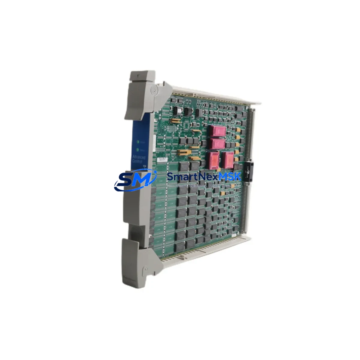
Honeywell 51304518-150 Maintenance-Ready Spare for TDC 3000 Automation
The Honeywell 51304518-150 is an original DCS control module engineered for the TDC 3000 distributed control system — one of the most widely deployed process automation platforms in refining, petrochemical, and continuous manufacturing environments. For maintenance engineers managing aging TDC 3000 infrastructure, sourcing a verified, in-stock replacement for the 51304518-150 is often the single most critical step in restoring process control after an unplanned shutdown. This listing provides a genuine, tested spare with full 12-month warranty coverage, ready for immediate dispatch.
Unplanned downtime in DCS-controlled processes carries significant operational and financial risk. A failed control module in a TDC 3000 cabinet can cascade into loss of loop control, alarm flooding, and forced manual override — conditions that maintenance teams must resolve within hours, not days. Stocking the 51304518-150 as a certified spare eliminates the lead-time risk associated with OEM procurement channels and ensures your maintenance team can execute a like-for-like swap without system reconfiguration.
Spare Maintenance Table
| Parameter | Specification |
|---|---|
| Part Number / SKU | 51304518-150 |
| Manufacturer | Honeywell Process Solutions |
| Compatible System | TDC 3000 Distributed Control System |
| Module Type | DCS Control Module |
| Form Factor | Card / Board Module (rack-mounted) |
| Operating Voltage | 24 VDC (nominal, per TDC 3000 backplane) |
| Operating Temperature | 0°C to 60°C (standard industrial enclosure) |
| Backplane Compatibility | TDC 3000 standard card cage / backplane |
| Installation Method | Direct card-cage insertion, no tools required |
| Communication Interface | Local Control Network (LCN) / UCN per TDC 3000 architecture |
| Condition | Original / Refurbished — 100% function-tested before shipment |
| Country of Origin | United States |
| Weight | 720 g |
| Warranty | 12 Months from date of shipment |
| Lead Time | In stock — ships within 1–3 business days |
| Application Environment | Refining, Petrochemical, Power Generation, Continuous Process Manufacturing |
| Maintenance Recommendation | Inspect backplane connectors and card-cage bus contacts at each planned maintenance interval; replace fuses and verify power rail voltages before module insertion |
Maintenance Planning for Continuous Operation
Replacing the 51304518-150 in a live TDC 3000 system is rarely an isolated task. Experienced maintenance engineers know that a module failure is often a symptom of broader electrical stress in the control cabinet. Before and after installing the replacement module, a structured inspection of the surrounding components is essential to prevent repeat failures and protect the new spare.
Start with the power supply module feeding the card cage — TDC 3000 systems typically use dedicated 24 VDC power supply units (such as the Honeywell 51190076-100 or equivalent series) that should be load-tested and inspected for capacitor aging. A degraded power supply is a leading cause of premature module failure. Verify that all backplane bus connectors are clean and free of oxidation; corroded backplane contacts can cause intermittent communication faults that mimic module failure.
Inspect the Local Control Network (LCN) coaxial cable terminations and any associated network interface modules in the same cabinet. A marginal LCN connection can cause the replacement 51304518-150 to report communication errors immediately after installation. If the system uses Universal Control Network (UCN) highway interface modules, verify their firmware revision compatibility with the replacement card.
Check all I/O termination assemblies (TAs) and field termination assemblies (FTAs) connected to the module’s I/O channels. Loose or corroded terminal connections at the FTA level are a common source of signal errors that can be misattributed to the control module itself. While the cabinet is open, inspect fuse holders and fuse blocks on the I/O power rails — blown or high-resistance fuses on field power circuits are frequently overlooked during emergency replacements.
For systems with signal conditioning or signal isolation modules in the I/O chain, verify that isolator output ranges remain within calibrated limits. Aging signal isolators can introduce offset errors that become apparent only after a control module swap restores accurate A/D conversion. Similarly, inspect any relay output modules or solid-state relay (SSR) assemblies associated with the affected control loops — a welded relay contact or failed SSR can cause loop output anomalies that are incorrectly attributed to the new module.
Finally, confirm that the HMI workstation or operator console connected to the TDC 3000 system has been updated with the correct module configuration data. In some TDC 3000 installations, the History Module (HM) or Application Module (AM) may require a configuration reload after a control module replacement to restore trend data collection and alarm setpoint assignments.
Site Replacement Workflow
A structured replacement workflow minimizes downtime and reduces the risk of introducing new faults during the swap. Follow these steps when replacing the 51304518-150 in a TDC 3000 system:
1. Pre-replacement verification: Confirm the failed module’s slot address and node number in the TDC 3000 system database. Document all active loop assignments, alarm setpoints, and control parameters associated with the module before removal. Take a photograph of the card-cage slot and wiring for reference.
2. Safe removal: Place affected control loops in manual mode at the operator console before extracting the module. This prevents process upsets caused by loss of automatic control during the swap. If the module is hot-swappable in your TDC 3000 configuration, follow the OEM hot-swap procedure; otherwise, coordinate a controlled shutdown of the affected card cage.
3. Inspection before insertion: Inspect the replacement 51304518-150 for shipping damage. Verify the firmware label or revision marking matches the system’s requirements. Clean the card-edge connector with isopropyl alcohol if necessary. Confirm backplane slot contacts are clean and undamaged.
4. Module insertion and initialization: Insert the replacement module firmly into the card-cage slot. Observe the module’s LED status indicators during power-up — a healthy TDC 3000 module will cycle through its self-test sequence and report a ready status within 60–90 seconds. If fault LEDs remain active, do not return loops to automatic mode; consult the TDC 3000 fault isolation guide.
5. System validation: Return control loops to automatic mode one at a time, monitoring process variable (PV) and output (OP) values for stability. Verify alarm setpoints and trend data are correctly restored. Confirm LCN/UCN communication status at the system console before closing the cabinet.
6. Documentation: Record the replacement in the plant maintenance management system (CMMS) with the new module’s serial number, installation date, and post-replacement test results. Update the spare parts inventory to trigger reorder of a replacement 51304518-150 for the next maintenance cycle.
Spare Parts Support FAQ
Q1: Is the 51304518-150 compatible with all TDC 3000 system revisions?
The 51304518-150 is designed for the Honeywell TDC 3000 platform and is compatible with the standard TDC 3000 card-cage and backplane architecture. Compatibility with specific firmware revisions or system software versions should be verified against your site’s TDC 3000 system documentation or Honeywell engineering records. We recommend confirming the module revision level with our technical team before ordering if your system is running a non-standard software release.
Q2: How is the module tested before shipment?
Every 51304518-150 unit is function-tested on a compatible TDC 3000 test bench prior to shipment. Testing covers power-up self-test completion, communication interface verification, and I/O channel continuity checks. A test report is available upon request. Units are shipped in anti-static packaging with physical protection to prevent transit damage.
Q3: What does the 12-month warranty cover?
The 12-month warranty covers manufacturing defects and functional failures under normal operating conditions from the date of shipment. It does not cover damage caused by incorrect installation, overvoltage events, physical impact, or use outside the module’s rated environmental specifications. Warranty claims are processed with a replacement unit dispatched after the failed module is returned and inspected. Contact [email protected] to initiate a warranty claim.
Q4: Can I order multiple units for long-term spare parts inventory?
Yes. We support bulk spare parts orders for maintenance departments building strategic inventory for TDC 3000 systems. Volume pricing is available for orders of 3 or more units. Long-term supply agreements can be arranged for facilities with ongoing TDC 3000 maintenance programs. Contact our team to discuss inventory reservation, staged delivery, and multi-unit pricing options.
© 2026 SMARTNEXMSK. All rights reserved.
Original Source: https://smartnexmsk.com
Contact: [email protected] | +86 18259474341



