
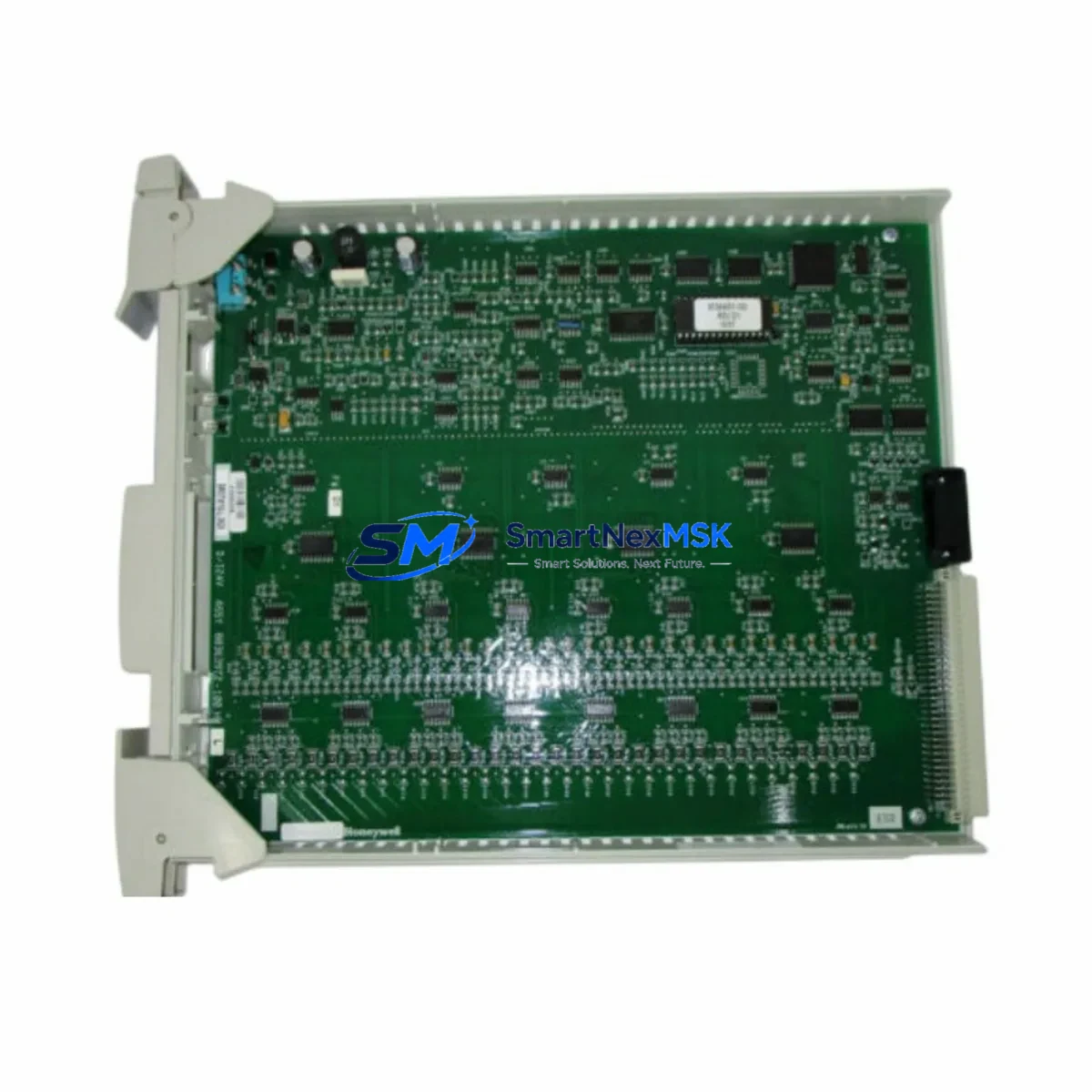
Honeywell 51401135-300 Retrofit-Ready Redundant PSU for TDC 3000 Control Systems
The Honeywell 51401135-300 is a retrofit-ready redundant power supply module engineered for seamless integration into legacy TDC 3000 Distributed Control System architectures. As process plants face increasing pressure to extend the operational life of existing control infrastructure while managing obsolescence risk, the 51401135-300 provides a verified drop-in replacement path that eliminates the need for full platform migration. Whether you are restoring a failed power rail, upgrading aging PSU modules in a redundant pair, or consolidating spare parts inventory ahead of a planned turnaround, this module delivers the electrical performance and form-factor compatibility required for a low-risk, minimum-downtime retrofit.
Upgrade Compatibility Table
| Parameter | Details |
|---|---|
| Compatible Platform | Honeywell TDC 3000 DCS |
| Module Type | Redundant Power Supply Module |
| SKU / Part Number | 51401135-300 |
| Installation Interface | Standard TDC 3000 power chassis backplane slot |
| Communication Compatibility | Passive power rail — no protocol dependency |
| Replacement Recommendation | Direct replacement for failed or end-of-life PSU in redundant pair |
| Commissioning Notes | Verify DC output voltage, load balance between redundant pair, and chassis grounding before energizing |
| Warranty | 12-Month Warranty included |
Retrofit Planning for Existing Automation Systems
Successful integration of the 51401135-300 into an operating TDC 3000 system requires careful pre-installation planning across several interdependent subsystems. Engineers should begin by auditing the existing power chassis to confirm available slot positions and verifying that the backplane connectors are free of corrosion or mechanical damage. The module must be matched against the current load profile of the control cabinet — particularly when the TDC 3000 system is hosting a dense I/O configuration that includes Honeywell PM I/O Link modules, analog input/output cards, and High-Performance Process Manager (HPM) controllers drawing sustained current.
Terminal wiring adaptation is a common challenge during retrofit. Technicians should cross-reference the existing field wiring termination blocks against the new module’s connector pinout to confirm polarity and grounding continuity. In systems where the TDC 3000 is interfaced with a Universal Control Network (UCN) or Local Control Network (LCN), the power supply upgrade must not interrupt the network communication backbone — UCN coaxial cable segments and LCN fiber-optic links should be verified for signal integrity before and after the swap.
For plants running Honeywell’s Application Module (AM) or History Module (HM) on the same LCN segment, it is advisable to schedule the PSU replacement during a planned maintenance window and to pre-stage a tested spare. The 51401135-300 is also commonly deployed alongside Honeywell 51401196-100 power distribution assemblies and 51304485-100 chassis backplane assemblies, which should be inspected for wear during the same maintenance cycle. Where the control system includes a Honeywell Data Hiway Gateway or a Hiway Interface Module (HIM), confirming that the gateway remains powered through an independent UPS circuit during the PSU swap is essential to maintaining historian continuity and alarm management integrity.
Plants upgrading from earlier TDC 2000 architectures to TDC 3000 will find the 51401135-300 particularly relevant as a bridging component during phased migration, where legacy I/O marshalling panels are being re-terminated to new HPM I/O Link assemblies. In these scenarios, the power supply must support the transient load spikes associated with simultaneous I/O scanning across multiple Honeywell PM I/O cards. Inventory of related components — including Honeywell 51401469-200 fuse assemblies and 51190076-100 power filter modules — should be confirmed before commencing the retrofit to avoid secondary delays.
Downtime Control During System Migration
Minimizing unplanned downtime during a PSU retrofit on a live TDC 3000 system requires a structured hot-swap or cold-swap protocol depending on the redundancy state of the existing power pair. Where a healthy redundant partner module is confirmed operational, the 51401135-300 can be installed in the failed slot without de-energizing the chassis, provided the plant’s safety procedures permit live-chassis work. The replacement module should be pre-tested on a bench power supply to confirm output voltage regulation before insertion.
Prior to any swap, the control engineer should export a full checkpoint of the TDC 3000 database — including all HPM controller configurations, AM application logic, and HM historian tag definitions — to a secure backup location. This ensures that in the event of an unexpected system reset, the original program logic, PID tuning parameters, and HMI display configurations can be restored without manual re-entry. Operators should be briefed to monitor the HMI overview displays for any transient alarm floods during the power transition, and suppression windows should be pre-configured where the DCS supports it.
Post-installation, the commissioning checklist should include: output voltage verification under full load, redundancy switchover test, chassis temperature monitoring, and a 24-hour soak period with alarm logging active. All findings should be documented in the plant’s maintenance management system to support future audit trails and warranty claims under the 12-month warranty coverage provided with the 51401135-300.
Retrofit Support FAQ
Q: Is the 51401135-300 a direct drop-in replacement for the original Honeywell TDC 3000 power supply?
A: Yes. The 51401135-300 is designed as a form-fit-function replacement for the original TDC 3000 redundant power supply module. No chassis modification or firmware update is required for standard installations.
Q: What commissioning steps are required after installation?
A: After seating the module, verify DC bus voltage at the chassis test points, confirm load sharing between the redundant pair, perform a manual redundancy switchover test, and monitor system alarms for a minimum of 30 minutes before returning the unit to normal operation.
Q: How do I confirm wiring compatibility before installation?
A: Cross-reference the 51401135-300 connector pinout against your existing field wiring documentation. Pay particular attention to DC return grounding, chassis earth bonding, and any local isolation requirements specified in your plant’s electrical safety procedures.
Q: What does the 12-month warranty cover?
A: The 12-month warranty covers manufacturing defects and functional failures under normal operating conditions. Each unit undergoes pre-shipment functional testing. Warranty claims are supported directly through our technical team with documented RMA procedures.
© 2026 SMARTNEXMSK. All rights reserved.
Original Source: https://smartnexmsk.com
Contact: [email protected] | +86 18259474341



