
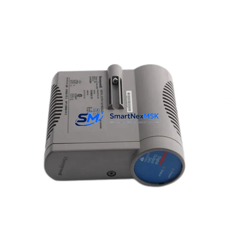
Honeywell 51402592-100 Maintenance-Ready Spare for TDC 3000 Automation
The Honeywell 51402592-100 is an original DCS interface module engineered for continuous-duty operation within Honeywell TDC 3000 and TPS (Total Plant Solution) distributed control systems. For maintenance engineers managing aging process control infrastructure, this module represents a critical line-of-defence against unplanned downtime. Whether you are executing a scheduled turnaround, responding to a fault alarm, or building a strategic spare-parts buffer, the 51402592-100 delivers verified compatibility, traceable provenance, and a 12-month warranty — giving your team the confidence to restore control loops quickly and safely.
Industrial facilities running TDC 3000 platforms face an increasingly narrow supply window for original hardware. Sourcing a genuine 51402592-100 from a qualified distributor — rather than relying on field-repaired or counterfeit units — eliminates the risk of introducing latent faults into a live control environment. Every unit shipped by SMARTNEXMSK undergoes functional verification and burn-in testing before dispatch, with full documentation available on request.
Spare Maintenance Table
| Parameter | Specification / Detail |
|---|---|
| Part Number | 51402592-100 |
| Manufacturer | Honeywell Process Solutions |
| Series Compatibility | TDC 3000, TPS (Total Plant Solution) |
| Module Function | DCS Interface Module — I/O signal conditioning and bus communication |
| Form Factor | Card-cage / backplane-mounted module |
| Power Supply Requirement | Supplied via TDC 3000 card-cage backplane (24 VDC nominal) |
| Signal Interface | Analog and discrete I/O compatible with TDC 3000 UCN/LCN architecture |
| Operating Temperature | 0 °C to 60 °C (32 °F to 140 °F) |
| Humidity | 5% to 95% RH, non-condensing |
| Installation Environment | Control room / marshalling cabinet; IEC 61010-compliant enclosure recommended |
| Replacement Scope | Direct drop-in for failed or end-of-life 51402592-100 units |
| Firmware / Configuration | Retains existing node configuration when installed in same slot |
| Pre-shipment Testing | Functional verification and burn-in test performed on every unit |
| Warranty | 12 Months — covers manufacturing defects and functional failure under normal operating conditions |
| Lead Time | In-stock units ship within 2 business days; long-term supply agreements available |
Maintenance Planning for Continuous Operation
When a 51402592-100 interface module is flagged during a routine control-cabinet inspection or triggers a diagnostic alarm on the Honeywell operator station, experienced maintenance engineers know that the fault rarely exists in isolation. A systematic inspection of the surrounding hardware is essential before returning the loop to service.
Begin by verifying the TDC 3000 card-cage power supply module — typically a 51401469-100 or equivalent — since a marginal power rail is a common root cause of interface module failures and will damage a replacement unit if left uncorrected. Next, inspect the UCN (Universal Control Network) cable and termination resistors; a degraded UCN segment can cause intermittent communication faults that mimic module failure. Check the backplane connector pins for oxidation or mechanical damage before seating the new 51402592-100.
On the field-wiring side, review the marshalling cabinet terminal blocks (such as Honeywell 51109684-100 series) for loose terminations, corrosion, or insulation breakdown. If the module interfaces with analog input channels, inspect the associated signal isolators or barriers — Zener barriers or galvanic isolators — to confirm they are within calibration and not contributing to signal drift. For discrete I/O loops, verify the relay output modules (e.g., 51304485-100 series) and associated fuse holders in the same cabinet section.
Where the 51402592-100 participates in a redundant controller pair, confirm that the partner module (primary or secondary) is healthy and that the switchover logic has not been compromised. Review the LCN (Local Control Network) node address configuration on the replacement module against the system database before energising. For plants running Honeywell’s Application Module (AM) or History Module (HM) on the same LCN segment, a brief network health check via the GUS (Global User Station) or HMI console is recommended after module swap to confirm all nodes are communicating normally.
Finally, update your CMMS (Computerised Maintenance Management System) spare-parts record to reflect the replacement event, and consider stocking a second 51402592-100 unit as a fast-response buffer — particularly for facilities where the TDC 3000 platform supports critical process units with high downtime cost.
Site Replacement Workflow
Step 1 — Isolation and permit: Obtain a Permit to Work (PTW) and place the affected control loop in manual or bypass mode at the operator station. Confirm with the process team that the loop output is held safely before proceeding.
Step 2 — Module extraction: With the card cage powered (hot-swap capability varies by TDC 3000 configuration — verify your site’s procedure), release the module locking lever and extract the 51402592-100 using the card extractor tool. Avoid touching the backplane connector pins. Place the removed module in an ESD-protective bag immediately.
Step 3 — Visual and connector inspection: Inspect the card-cage slot for debris, bent pins, or signs of thermal stress. Clean with dry compressed air if required. Confirm the replacement 51402592-100 part number and revision level match the system database entry.
Step 4 — Installation and configuration verification: Seat the replacement module firmly until the locking lever engages. Allow the module to complete its self-test sequence (typically 30–60 seconds). Confirm the module status LED indicates normal operation and that the operator station shows the node as online.
Step 5 — Loop restoration and functional test: Return the control loop to automatic mode. Verify process variable (PV), setpoint (SP), and output (OP) readings are consistent with pre-fault values. Document the replacement in the site maintenance log and update the spare-parts inventory accordingly.
This workflow minimises mean time to repair (MTTR) and ensures the TDC 3000 system is returned to full operational status with a verified, warranted component — reducing the risk of repeat failures and supporting long-term system life extension beyond the original product lifecycle.
Spare Parts Support FAQ
Q1: Is the 51402592-100 still in production, and how do you ensure long-term supply?
Honeywell has transitioned many TDC 3000 components to end-of-life status, but SMARTNEXMSK maintains a managed inventory of original, factory-sourced 51402592-100 units. We actively source from verified channels to support facilities committed to extending TDC 3000 platform life. Long-term supply agreements are available for customers requiring guaranteed stock over a multi-year horizon.
Q2: How is compatibility with my specific TDC 3000 or TPS configuration verified before shipment?
Provide your system revision level, card-cage type, and slot assignment when placing your order. Our technical team cross-references this against the module’s hardware revision and firmware compatibility matrix. Every unit is functionally tested prior to dispatch, and a test report is available upon request.
Q3: Can the 51402592-100 be installed as a hot-swap replacement without a full system shutdown?
Hot-swap capability depends on your specific TDC 3000 card-cage model and site safety procedures. Many TDC 3000 configurations support online module replacement; however, we strongly recommend consulting your Honeywell system documentation and obtaining the appropriate PTW before any live-cabinet intervention. Our technical support team can advise on site-specific replacement procedures.
Q4: What does the 12-month warranty cover, and what is the returns process?
The 12-month warranty covers manufacturing defects and functional failure under normal operating conditions from the date of shipment. It does not cover damage resulting from incorrect installation, overvoltage events, or physical mishandling. To initiate a warranty claim, contact [email protected] with your order reference and a description of the fault. We will arrange collection, inspection, and replacement or repair within an agreed lead time.
© 2026 SMARTNEXMSK. All rights reserved.
Original Source: https://smartnexmsk.com
Contact: [email protected] | +86 18259474341



