
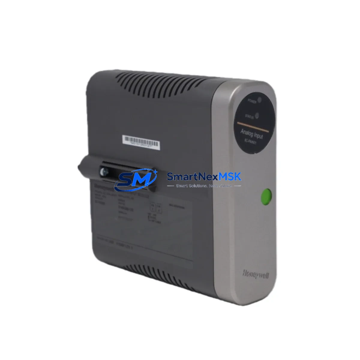
Honeywell 8C-PDOD51 Retrofit-Ready Digital Output for TDC 3000 Control Systems
The Honeywell 8C-PDOD51 is a 24 VDC Digital Output Module engineered for the TDC 3000 TotalPlant Distributed Control System platform. As legacy TDC 3000 installations approach end-of-support milestones, plant engineers and automation integrators increasingly rely on verified, drop-in-compatible modules like the 8C-PDOD51 to extend operational life, reduce unplanned downtime, and defer full-system migration costs. Whether you are replacing a failed output card, upgrading a degraded I/O subsystem, or consolidating spare-parts inventory across multiple control cabinets, the 8C-PDOD51 delivers the signal integrity, backplane compatibility, and firmware alignment required for seamless integration into existing TDC 3000 architectures.
SMARTNEXMSK maintains verified stock of the 8C-PDOD51 with full functional testing prior to shipment. Each unit undergoes output channel verification, backplane connector inspection, and LED status confirmation. All units ship with a 12-month warranty covering manufacturing defects and functional failures under normal operating conditions.
Upgrade Compatibility Table
| Parameter | 8C-PDOD51 Specification | Retrofit Notes |
|---|---|---|
| Module Type | Digital Output (DO), 24 VDC | Direct replacement for same-type DO slots in TDC 3000 I/O cabinets |
| Output Channels | 8 channels per module | Channel mapping must be verified against existing I/O assignment tables before hot-swap |
| Backplane Interface | TDC 3000 standard I/O bus connector | Compatible with standard TDC 3000 I/O carrier and extender backplanes |
| Communication Protocol | TDC 3000 proprietary I/O bus | No protocol conversion required; plug-and-play within TDC 3000 I/O subsystem |
| Installation Requirement | Keyed module slot, no tools required | Confirm slot key orientation matches cabinet configuration before insertion |
| Replacement Compatibility | Drop-in for 8C-PDOD51 and functionally equivalent DO modules | Verify firmware revision compatibility with UCN/LCN node software version |
| Commissioning Focus | Output channel address, load verification, interlock logic check | Re-download I/O configuration from Engineering Workstation after module swap |
| Warranty | 12 Months | Covers functional failure under normal DCS operating conditions |
Retrofit Planning for Existing Automation Systems
Successful integration of the 8C-PDOD51 into a live TDC 3000 system requires systematic pre-installation planning. Begin by auditing the target I/O cabinet to confirm available slot positions, backplane revision, and power budget. The TDC 3000 I/O Power Supply Module (typically a redundant 24 VDC rail configuration) must have sufficient headroom to support the additional output load introduced by the replacement module. If the cabinet is operating near capacity, consider redistributing loads across adjacent I/O carriers before proceeding.
Next, retrieve the current I/O assignment database from the Honeywell Engineering Workstation (EWS) or the Universal Control Network (UCN) node configuration files. Cross-reference the 8C-PDOD51 slot address with the existing channel-to-field-device mapping to ensure no address conflicts exist with neighboring modules such as the 8C-PDID51 Digital Input Module or 8C-PAIH51 Analog Input Module. Address conflicts in TDC 3000 I/O subsystems can cause silent output failures that are difficult to diagnose during live operation.
For cabinets that also house Honeywell PM/APM Process Manager controllers or Logic Manager (LM) nodes, confirm that the controller firmware version supports the 8C-PDOD51 module descriptor. Older APM firmware revisions may require a patch download from the EWS before the new module is recognized correctly on the I/O bus. This step is especially critical in plants that have not performed a controller firmware refresh in more than five years.
Wiring adaptation is another key consideration. The 8C-PDOD51 uses a standard TDC 3000 field termination assembly. If the existing Field Termination Assembly (FTA) or marshalling panel wiring was configured for a different output module variant, terminal block re-labeling and continuity testing are required before energizing the outputs. Use a calibrated loop tester to verify each output channel against the field device — typically solenoid valves, motor starters, or relay coils — before enabling the channel in the control strategy.
Where the retrofit scope extends beyond a single module swap to include Honeywell HLAI/LLAI Analog Output Modules, 8C-TAOX15 Analog Output Termination Assemblies, or communication gateway upgrades involving the Honeywell OPC Server or PHD Historian interface, a phased migration plan is strongly recommended. Phased execution allows each subsystem to be validated independently, reducing the risk of cascading failures during cutover.
Downtime Control During System Migration
Minimizing production downtime during a TDC 3000 module replacement requires a structured hot-swap or planned-outage protocol. For non-redundant output channels, coordinate with operations to place the affected control loop in manual mode at the Honeywell GUS (Global User Station) or operator console before removing the module. Document the current output state — percentage open, energized/de-energized — so the field device can be manually held at the correct position during the swap interval.
For redundant I/O configurations using paired DO modules, the standby module can absorb the load while the primary is replaced, reducing the cutover window to under five minutes in most cases. After reinserting the 8C-PDOD51, allow the TDC 3000 I/O bus to complete its self-diagnostic cycle — typically 15 to 30 seconds — before transferring control back to automatic mode. Monitor the System Status Display on the GUS for any fault annunciations related to the new module’s channel initialization.
Preserve the original control strategy database and HMI faceplate configurations throughout the migration. The 8C-PDOD51 replacement does not require changes to existing Control Language (CL) programs or Detail Display graphics, provided the module address and channel assignments remain identical. If address reassignment is unavoidable due to cabinet reconfiguration, update the I/O assignment tables in the EWS and perform a full database consistency check before returning the loop to automatic control.
For plants managing multiple simultaneous module replacements across several I/O cabinets, a staged rollout — replacing one cabinet section per maintenance window — is the most effective strategy for maintaining overall system availability while progressively modernizing the I/O infrastructure.
Retrofit Support FAQ
Q1: Is the 8C-PDOD51 a direct drop-in replacement for the original Honeywell TDC 3000 digital output module?
Yes. The 8C-PDOD51 is designed as a form-fit-function replacement for the original TDC 3000 DO module position. No backplane modification or wiring change is required when replacing a like-for-like module in the same slot. Confirm the module key orientation and slot address before insertion.
Q2: What commissioning steps are required after installing the 8C-PDOD51?
After physical installation, re-download the I/O configuration from the Engineering Workstation to ensure the module descriptor is correctly loaded. Perform a channel-by-channel output verification using the GUS force function or a portable loop tester. Confirm all interlock and shutdown logic associated with the replaced channels is functioning correctly before returning to automatic mode.
Q3: How do I verify wiring compatibility between the 8C-PDOD51 and my existing Field Termination Assembly?
Compare the FTA model number against the 8C-PDOD51 compatibility matrix in the Honeywell TDC 3000 I/O Hardware Reference Manual. If the FTA was originally installed for the same module type, no wiring changes are required. For cross-type FTA configurations, re-terminate the field wiring to match the 8C-PDOD51 terminal assignment and perform continuity and insulation resistance tests before energizing.
Q4: What does the 12-month warranty cover?
The 12-month warranty covers functional failures attributable to manufacturing defects, including output channel failure, backplane connector faults, and internal component failures under normal DCS operating conditions. It does not cover damage resulting from incorrect installation, overvoltage events, or physical mishandling. Warranty claims are processed through SMARTNEXMSK with a standard RMA procedure and replacement turnaround of 5–7 business days.
© 2026 SMARTNEXMSK. All rights reserved.
Original Source: https://smartnexmsk.com
Contact: [email protected] | +86 18259474341



