
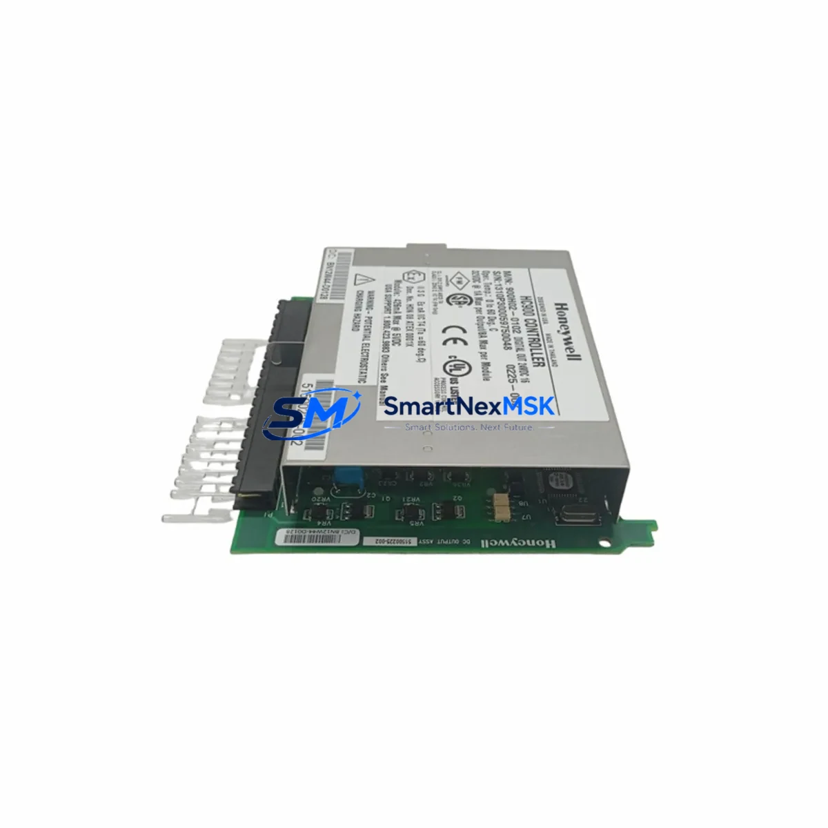
Honeywell 900H02-0102 Spare for HC900 Automation: Spare Replacement & Industrial Downtime Risk Control
The Honeywell 900H02-0102 is a 16-channel digital output module designed for the HC900 Hybrid Controller platform — one of Honeywell’s most widely deployed process automation systems in refining, chemical, power, and utilities industries. As a maintenance-ready original spare, the 900H02-0102 supports direct plug-and-play replacement in existing HC900 rack assemblies without requiring firmware reconfiguration or system re-commissioning, making it a critical component for any site-level spare parts inventory strategy.
For maintenance engineers managing aging HC900 installations, securing a verified replacement 900H02-0102 is essential to minimizing unplanned downtime. Digital output modules are among the highest-wear components in any control cabinet — subject to coil cycling, inductive load stress, and thermal fatigue over extended service life. Proactive stocking of this module, alongside associated power supply modules such as the 900P01-0001 and rack backplane assemblies, ensures that a single module failure does not cascade into a multi-day production outage.
Spare Maintenance Table
| Parameter | Specification |
|---|---|
| Part Number / SKU | 900H02-0102 |
| Brand | Honeywell |
| Series | HC900 Hybrid Controller |
| Module Type | 16-Channel Digital Output Module |
| Output Type | Relay / Solid-State (site-dependent configuration) |
| Compatibility | HC900 Rack Assemblies (900R08-0001, 900R16-0001) |
| Installation | Plug-and-play, hot-swap capable in supported rack configurations |
| Operating Voltage | 24 VDC nominal (rack-supplied) |
| Operating Temperature | 0°C to 60°C |
| Certifications | CE, UL (per Honeywell HC900 platform certification) |
| Application Environment | Process automation, utilities, refining, chemical plants |
| Maintenance Recommendation | Inspect output channel status LEDs quarterly; replace on first sign of channel dropout |
| Warranty | 12 Months from date of shipment |
| Condition | Original, factory-tested, ready to ship |
Maintenance Planning for Continuous Operation
When scheduling a planned replacement of the 900H02-0102 Digital Output Module, maintenance and procurement engineers should treat the event as an opportunity for a broader HC900 control cabinet inspection. The digital output module does not operate in isolation — its reliability depends on the health of several interconnected components within the same electrical circuit and rack assembly.
Begin with the HC900 power supply module (900P01-0001): verify output voltage stability under load before inserting the replacement module. A degraded power supply is a leading cause of premature output module failure and will shorten the service life of a new spare. Next, inspect the rack backplane (900R08-0001 or 900R16-0001) for connector pin corrosion or mechanical damage — a faulty backplane connector can cause intermittent channel faults that are often misdiagnosed as module failure.
On the field wiring side, check all terminal blocks and field wiring harnesses connected to the output module’s I/O terminals. Loose terminations and insulation degradation are common in high-cycle output circuits. If the site uses interposing relay modules (such as Phoenix Contact or Weidmüller DIN-rail relay bases) between the 900H02-0102 outputs and field actuators, inspect relay coil resistance and contact wear — these relays typically require replacement every 500,000 to 1,000,000 operations.
For sites with HC900 communication modules (900C51-0243 or 900C52-0143) handling Modbus or Ethernet/IP supervisory links, verify that the replacement module is recognized by the controller after insertion and that all output channel tags are correctly mapped in the HC Designer configuration. If the site uses a Honeywell HMI or Experion PKS supervisory layer, confirm that output status displays update correctly post-replacement before returning the loop to automatic control.
Additionally, review any signal isolators or loop-powered barriers in the output circuit — particularly for intrinsically safe zones — to confirm they remain within calibration tolerance. Fuse holders and miniature circuit breakers (MCBs) protecting the output module’s field circuits should also be tested for correct trip characteristics, as nuisance tripping or failure-to-trip can both indicate aging protective devices that should be replaced concurrently.
Site Replacement Workflow
Step 1 — Pre-replacement verification: Confirm the replacement 900H02-0102 part number and firmware revision match the installed module. Cross-reference the HC900 system configuration file (HC Designer project) to verify slot assignment and I/O channel mapping.
Step 2 — Safe isolation: Place affected output loops in manual mode at the DCS/HMI level. De-energize field circuits via the appropriate MCB or fuse. Do not rely solely on software inhibit for high-energy output circuits.
Step 3 — Module extraction: Release the module locking tab and slide the 900H02-0102 from the rack slot. Inspect the backplane connector for damage before inserting the replacement unit.
Step 4 — Replacement insertion and verification: Insert the new module firmly until the locking tab engages. Power up the rack and confirm the module status LED indicates normal operation. Verify all 16 output channels are recognized in the HC Designer online view or HMI display.
Step 5 — Loop return to service: Re-energize field circuits sequentially. Test each output channel against its field device before returning loops to automatic control. Document the replacement in the site maintenance management system (CMMS) with the new module serial number and installation date.
This workflow minimizes exposure time and ensures system compatibility is confirmed before full production resumption — typically achievable within 30–60 minutes for a prepared maintenance team with the spare module on hand.
Spare Parts Support FAQ
Q1: Is the 900H02-0102 compatible with all HC900 rack sizes?
Yes. The 900H02-0102 is compatible with both the 8-slot (900R08-0001) and 16-slot (900R16-0001) HC900 rack assemblies. Slot assignment is configured in HC Designer and does not require hardware modification. Always verify the rack firmware revision is current before inserting a replacement module.
Q2: What pre-shipment testing is performed on the 900H02-0102?
Each unit undergoes functional output channel verification and power-on self-test prior to shipment. Modules are inspected for connector integrity, LED functionality, and physical condition. A test report is available upon request. All units ship with a 12-month warranty covering manufacturing defects and functional failure under normal operating conditions.
Q3: How should the 900H02-0102 be stored as a long-term spare?
Store in original anti-static packaging in a dry, temperature-controlled environment (10°C–40°C, <85% RH non-condensing). Avoid proximity to strong magnetic fields or high-vibration areas. Inspect stored spares annually for connector oxidation. Modules stored correctly retain full functionality for 5+ years.
Q4: Can the 900H02-0102 replace older or discontinued Honeywell HC900 output module variants?
The 900H02-0102 is the current production variant for the HC900 16-channel digital output function. It is backward compatible with earlier HC900 system revisions provided the rack firmware meets the minimum supported version. For sites running legacy HC900 configurations, contact our technical team to confirm compatibility before ordering. Long-term supply availability is maintained to support extended system lifecycles beyond OEM end-of-sale dates.
© 2026 SMARTNEXMSK. All rights reserved.
Original Source: https://smartnexmsk.com
Contact: [email protected] | +86 18259474341



