
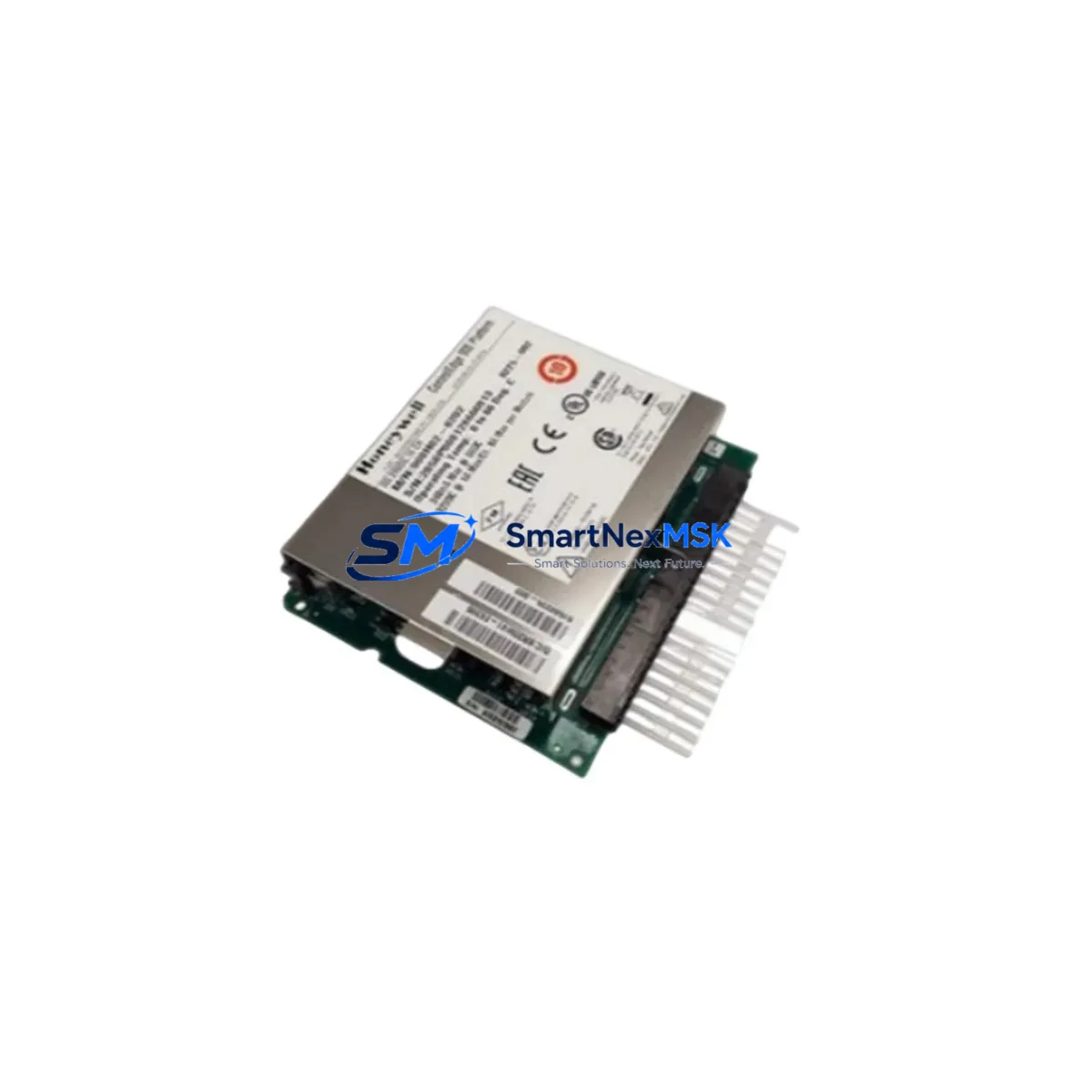
Honeywell 900H02-0202 Retrofit-Ready Digital Output for HC900 Control Systems
The Honeywell 900H02-0202 is a 16-channel, 24 VDC digital output module engineered for the HC900 Hybrid Controller platform. As legacy HC900 installations age and original spare parts become increasingly scarce, the 900H02-0202 has emerged as the go-to retrofit solution for engineers tasked with modernizing distributed control cabinets, upgrading I/O infrastructure, and restoring system availability without a full platform migration. Whether you are replacing a failed unit on an active production line or pre-positioning stock for a planned turnaround, this module delivers the electrical compatibility, firmware alignment, and mechanical form factor required for a smooth, low-risk swap.
Sourced directly from verified industrial supply channels and subjected to pre-shipment functional testing, every 900H02-0202 unit shipped by SMARTNEXMSK is backed by a 12-month warranty covering manufacturing defects and operational failures under normal service conditions. Global logistics support ensures fast delivery to plant sites across Asia, Europe, and the Americas.
Upgrade Compatibility Table
| Parameter | Details |
|---|---|
| Module SKU | 900H02-0202 |
| Platform Compatibility | Honeywell HC900 Hybrid Controller Series |
| Output Channels | 16-channel digital output, 24 VDC |
| Backplane Interface | HC900 standard rack backplane connector (direct plug-in) |
| Installation Requirement | No hardware modification required; slot-compatible with HC900 rack |
| Communication Compatibility | Modbus RTU / Ethernet (via HC900 controller); no separate comm config needed |
| Replaces / Supersedes | 900H02-0201 (earlier revision); functionally equivalent for most HC900 applications |
| Retrofit Recommendation | Verify rack slot addressing and I/O map in HC Designer before hot-swap |
| Commissioning Focus | Output channel forcing test, field wiring continuity check, controller scan cycle validation |
| Warranty | 12 months from shipment date — manufacturing defects and operational failures covered |
Retrofit Planning for Existing Automation Systems
A successful HC900 retrofit begins well before the module arrives on site. Engineers should pull the existing I/O configuration from HC Designer and cross-reference the channel assignments mapped to the 900H02-0202 slot. In most installations, the digital output module shares a rack with the HC900 CPU module (900C52-0243) and one or more analog input modules such as the 900A16-0102, so confirming rack slot numbering and backplane power budget is the first critical step. The HC900 rack itself — typically a 900R08-0001 or 900R12-0001 chassis — must have sufficient available power capacity to support the replacement module at full channel load.
Terminal wiring on the 900H02-0202 follows the standard HC900 field termination block layout. Before disconnecting the existing module, photograph or document the field wiring at the terminal block, noting wire labels, signal polarities, and any shielding connections. If the installation uses a 900TK-0001 termination kit or equivalent marshalling panel, the field cables can remain connected during the module swap, significantly reducing reconnection time and the risk of miswiring.
For sites running Modbus TCP/IP communications through a 900G32-0001 Ethernet Gateway module, no communication reconfiguration is typically required after replacing a digital output module — the gateway and controller handle addressing transparently. However, if the plant network also integrates a Honeywell HC900 OPC server or a third-party SCADA system via the 900CS-0001 communication module, it is advisable to verify that the HMI tag database correctly reflects the output channel addresses before returning the loop to automatic control.
Sites upgrading from older HC900 revisions may also encounter compatibility questions around the 900H01-0204 digital input module installed in adjacent slots. While input modules are not directly affected by an output module replacement, confirming that the controller firmware version supports the installed mix of module revisions prevents unexpected diagnostic alarms during startup. Honeywell’s HC Designer software provides a module compatibility matrix that should be reviewed as part of any retrofit planning exercise.
For larger-scale control cabinet upgrades involving multiple I/O replacements, it is common to simultaneously address the 900P01-0001 power supply module — particularly in installations where the existing power supply is approaching its rated service life. Replacing the power supply and I/O modules in a single planned outage minimizes total downtime and avoids a second maintenance window shortly after the initial retrofit.
Downtime Control During System Migration
Minimizing unplanned downtime is the primary operational concern during any HC900 module replacement. The recommended approach is to perform the swap during a scheduled maintenance window, with the controller placed in manual output mode prior to module removal. HC Designer allows operators to force individual output channels to a defined safe state — typically de-energized — before the physical swap begins, ensuring that field devices such as solenoid valves, motor starters, and indicator lamps remain in a known, safe condition throughout the procedure.
Before removing the 900H02-0202 from the rack, upload and save the current controller configuration to a backup file. This preserves the I/O map, PID tuning parameters, alarm setpoints, and communication settings in the event that the replacement module triggers a configuration mismatch alarm. In most cases, the controller will automatically recognize the new module and resume normal scan operation within one to two scan cycles after insertion — no program download is required if the module revision is compatible.
Post-installation commissioning should include a channel-by-channel output forcing test using HC Designer’s online monitoring mode, confirming that each of the 16 output channels energizes the correct field device. Verify loop continuity at the terminal block, check for any diagnostic LEDs indicating wiring faults, and confirm that the SCADA or HMI display reflects the correct output states before releasing the system to automatic control. Total swap time for an experienced technician, including pre-swap documentation and post-swap verification, typically ranges from 30 to 90 minutes depending on site conditions.
For critical processes where even a brief interruption is unacceptable, consider staging a pre-configured spare 900H02-0202 with the correct slot address programmed and verified offline, so that the physical installation step is reduced to a simple plug-and-confirm operation.
Retrofit Support FAQ
Q1: Is the 900H02-0202 a direct drop-in replacement for the 900H02-0201?
In the vast majority of HC900 applications, yes. The 900H02-0202 is the current production revision and is functionally equivalent to the 900H02-0201 for standard 16-channel 24 VDC digital output applications. We recommend verifying the module revision compatibility in HC Designer before installation, particularly in systems running older controller firmware versions.
Q2: Do I need to re-download the controller program after replacing the module?
Typically no. The HC900 controller recognizes the replacement module automatically during its next scan cycle. A program download is only required if the replacement module has a different hardware revision that is not recognized by the current firmware, or if the I/O configuration has been modified. Always back up the current configuration before beginning the swap.
Q3: How should I verify field wiring after installation?
Use HC Designer’s online channel forcing function to energize each output channel individually and confirm the corresponding field device responds correctly. Check terminal block connections for correct polarity, secure termination, and absence of ground faults. Review the module’s diagnostic LEDs for any fault indications before releasing to automatic control.
Q4: What does the 12-month warranty cover, and what is the return process?
The 12-month warranty covers manufacturing defects and operational failures under normal industrial service conditions. It does not cover damage resulting from incorrect installation, overvoltage, or physical mishandling. To initiate a warranty claim, contact [email protected] with your order number, a description of the fault, and photographic evidence of the defect. Replacement or repair will be arranged within 5 business days of claim approval.
© 2026 SMARTNEXMSK. All rights reserved.
Original Source: https://smartnexmsk.com
Contact: [email protected] | +86 18259474341



