
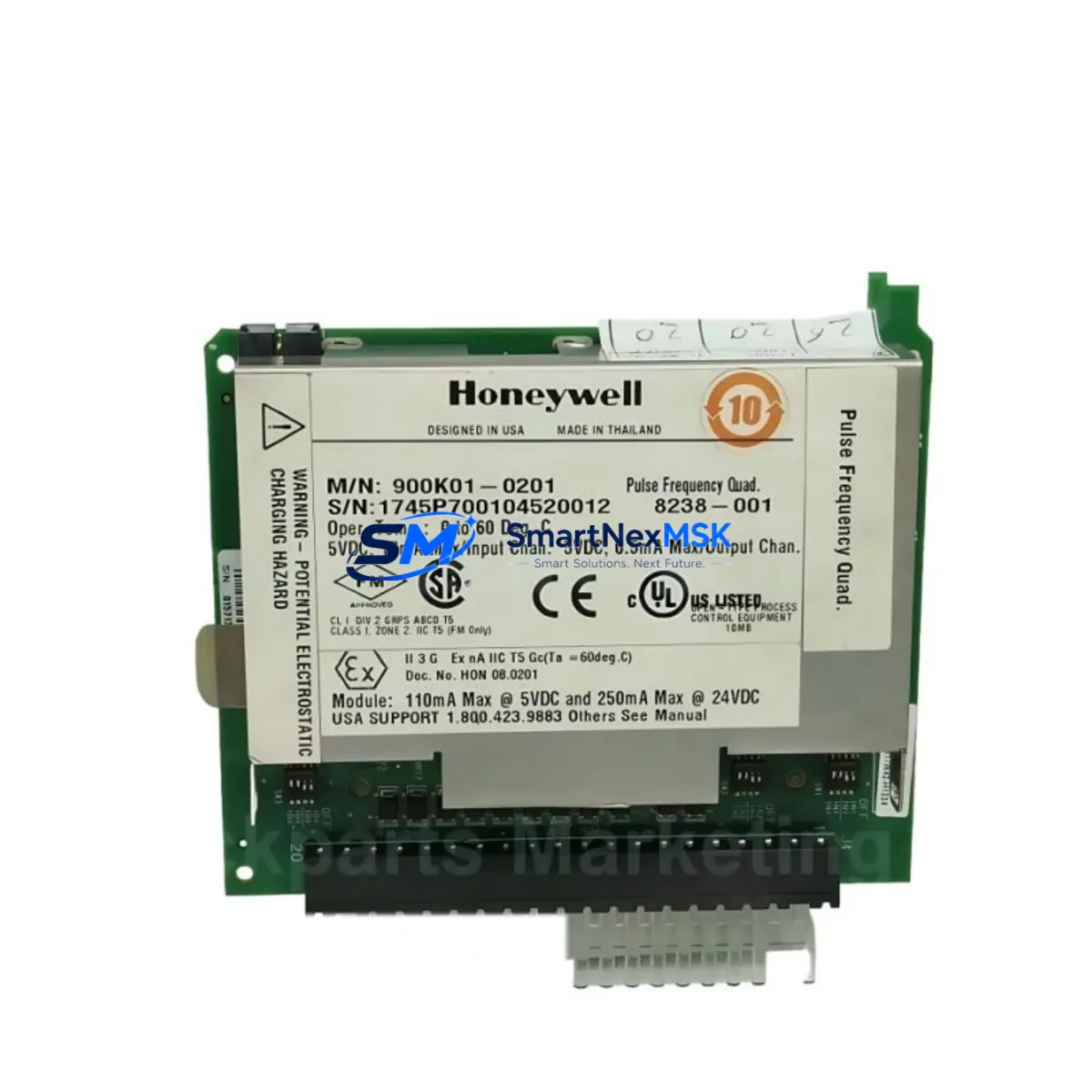
Honeywell 900RTC-3410 Retrofit-Ready RTP Cable for HC900 Control Systems
The Honeywell 900RTC-3410 is a high-voltage Remote Termination Panel (RTP) cable engineered for seamless integration into HC900 Hybrid Controller systems. Designed with retrofit compatibility as a core requirement, this cable supports direct drop-in replacement of legacy wiring assemblies without requiring panel redesign or backplane modification. For facilities managing aging DCS infrastructure, the 900RTC-3410 provides a reliable, specification-matched upgrade path that minimizes engineering risk and reduces planned downtime windows.
Industrial sites running HC900-based control architectures frequently encounter obsolescence challenges as original cable assemblies reach end-of-life. The 900RTC-3410 addresses this directly: its connector pinout, shielding specification, and conductor gauge are matched to the original Honeywell factory standard, ensuring that existing terminal blocks, marshalling panels, and I/O module interfaces accept the replacement without rework. Engineers performing control cabinet upgrades can install this cable alongside active components such as the HC900 Controller Module (900C71-0243-00), HC900 Scanner I/O Module (900CS-0001), and HC900 Analog Input modules without altering the surrounding wiring infrastructure.
When planning a retrofit around the 900RTC-3410, the following verification steps are critical before installation:
- Power Capacity: Confirm the existing 24 VDC power supply — typically a Honeywell HC900 Power Supply Module (900P01-0001) — can sustain the additional load introduced by any new I/O modules added during the upgrade cycle.
- Terminal Wiring: Verify field wiring termination points at the RTP against the original loop drawings. The 900RTC-3410 preserves the standard 37-pin D-sub interface, so no re-termination of field cables is required in most installations.
- Backplane Interface: Inspect the HC900 rack backplane for physical damage or oxidation at the module slot connectors before seating the replacement cable assembly.
- Module Addressing: Confirm I/O module slot addresses in the HC Designer configuration software are unchanged. Replacing a cable assembly does not alter module addressing, but any concurrent I/O expansion — such as adding a Honeywell HC900 Digital Output Module (900G32-0101) — requires address assignment review.
- Program Compatibility: Back up the existing HC900 controller program via HC Designer before beginning physical work. Verify that the program revision is compatible with the firmware version running on the 900C71 controller module.
- HMI Screen Integrity: If the site uses a Honeywell Station or third-party HMI connected via Modbus TCP or OPC, confirm that tag mappings referencing I/O points served by the RTP remain valid after the cable swap.
- Communication Links: For systems using Ethernet-based supervisory links to a Honeywell Experion PKS or a standalone SCADA platform, verify that the HC900 Ethernet Communication Module (900CS-0001) retains its IP configuration and that no network interruption occurs during the maintenance window.
- Field Commissioning: After installation, perform a loop check on all analog and digital channels served by the RTP. Use the HC Designer Force/Override function to validate signal integrity before returning the loop to automatic control.
Upgrade Compatibility Table
| Parameter | Detail |
|---|---|
| SKU | 900RTC-3410 |
| Brand / Series | Honeywell HC900 Hybrid Controller Series |
| Cable Type | High-Voltage Remote Termination Panel (RTP) Cable |
| Connector Interface | 37-pin D-sub (DB37), factory-standard pinout |
| Compatible Modules | HC900 Analog Input, Analog Output, Digital I/O modules; HC900 Scanner |
| Compatible Racks | HC900 4-slot and 12-slot I/O racks |
| Communication Compatibility | Modbus TCP, OPC DA/UA via HC900 Ethernet module |
| Installation Requirement | No panel redesign; direct drop-in replacement |
| Replacement Recommendation | Replaces OEM 900RTC-3410; compatible with all HC900 RTP-based I/O assemblies |
| Commissioning Note | Loop check required post-installation; HC Designer force function recommended |
| Warranty | 12 Months — covers manufacturing defects and connector integrity |
| Origin | CN (Xiamen stocking warehouse) |
| Stock Status | In Stock — ready to ship |
Retrofit Planning for Existing Automation Systems
A successful HC900 retrofit involving the 900RTC-3410 typically occurs within a broader system modernization effort. Control engineers frequently encounter scenarios where the RTP cable is the final legacy component preventing a full I/O subsystem upgrade. In these cases, the 900RTC-3410 serves as the bridge between the existing field wiring infrastructure and a refreshed I/O layer.
Common retrofit scopes that include the 900RTC-3410 also involve replacement of the Honeywell HC900 Power Supply Module (900P01-0001) when the original unit shows signs of capacitor aging or output voltage drift. Simultaneously, sites often upgrade their I/O complement by adding Honeywell HC900 Analog Input Modules (900A16-0101) for thermocouple or RTD inputs, or Honeywell HC900 Digital Input Modules (900G16-0101) to accommodate additional discrete field devices introduced during process expansion.
For facilities migrating from older Honeywell UDC or DC300 single-loop controllers to the HC900 platform, the 900RTC-3410 provides the physical wiring interface that allows reuse of existing marshalling cabinet terminal strips. This eliminates the need to re-pull field cables — a significant cost and schedule driver in brownfield projects. The HC900 Scanner I/O Module (900CS-0001) handles the communication bridge between the I/O rack and the main controller, and its compatibility with the 900RTC-3410 RTP interface is factory-verified.
Where the retrofit also involves HMI modernization — for example, replacing a legacy Honeywell Station with a current-generation operator interface or a third-party SCADA running on Windows Server — the HC900 Ethernet Communication Module supports Modbus TCP and OPC connectivity without requiring changes to the I/O wiring layer. Programming cable access via the HC900 USB Programming Cable allows on-site engineers to upload revised logic without interrupting field I/O scanning, provided the controller is placed in the appropriate operating mode.
Sites performing control cabinet upgrades alongside the cable replacement should also evaluate the HC900 Analog Output Module (900B08-0101) if the process requires additional final control element loops. All of these components share the same rack and backplane architecture, meaning the 900RTC-3410 RTP cable interfaces consistently across the entire HC900 I/O module family.
Downtime Control During System Migration
Minimizing unplanned downtime is the primary operational constraint in any brownfield control system retrofit. For the 900RTC-3410 replacement, the recommended approach is a pre-staged swap: the replacement cable assembly is tested on a bench or in a spare rack slot before the maintenance window begins, confirming connector integrity and continuity across all 37 pins.
During the maintenance window, the sequence is: (1) place the HC900 controller in Manual mode to freeze all output states; (2) document all analog and digital output values for manual hold at the field device level; (3) disconnect the legacy RTP cable and install the 900RTC-3410; (4) restore power and verify I/O module status LEDs; (5) perform a channel-by-channel loop check using HC Designer’s diagnostic view; (6) return loops to Automatic mode in a controlled sequence, starting with non-critical utility loops before process-critical control loops.
This sequence preserves the original program logic — no changes to the HC Designer project file are required for a like-for-like cable replacement. HMI tag mappings remain valid because the I/O module addresses and channel assignments are unchanged. Communication links to supervisory systems experience no interruption if the Ethernet module remains powered throughout the swap, which is achievable in most HC900 rack configurations where the power supply and communication modules occupy separate slots from the RTP-connected I/O modules.
For sites with zero-downtime requirements, a parallel installation approach using a spare HC900 rack pre-loaded with the 900RTC-3410 and a mirrored I/O configuration allows cutover in under 60 seconds by switching the field wiring termination at the marshalling panel rather than at the controller rack.
Retrofit Support FAQ
Q1: Is the 900RTC-3410 a direct replacement for the original Honeywell OEM cable?
Yes. The 900RTC-3410 is manufactured to the original Honeywell specification, including connector type, pinout, conductor gauge, and shielding. It installs directly into existing HC900 RTP-based I/O assemblies without modification to the panel, terminal blocks, or field wiring.
Q2: What commissioning steps are required after installation?
After physical installation, perform a full loop check on all analog and digital channels served by the RTP using HC Designer’s Force/Override diagnostic function. Verify that all I/O module status LEDs indicate normal operation and that the HC900 controller resumes scanning without fault codes. No program changes are required for a like-for-like replacement.
Q3: How is wiring compatibility verified before ordering?
Provide your existing cable part number, HC900 rack model, and I/O module types to our technical team at [email protected]. We will confirm compatibility against the HC900 system documentation and advise on any adapter requirements for non-standard panel configurations.
Q4: What does the 12-month warranty cover?
The 12-month warranty covers manufacturing defects, connector integrity failures, and conductor continuity issues under normal industrial operating conditions. Each unit undergoes outgoing inspection including continuity testing across all pins before shipment. Warranty claims are processed within 5 business days of receipt of the returned unit.
© 2026 SMARTNEXMSK. All rights reserved.
Original Source: https://smartnexmsk.com
Contact: [email protected] | +86 18259474341



