
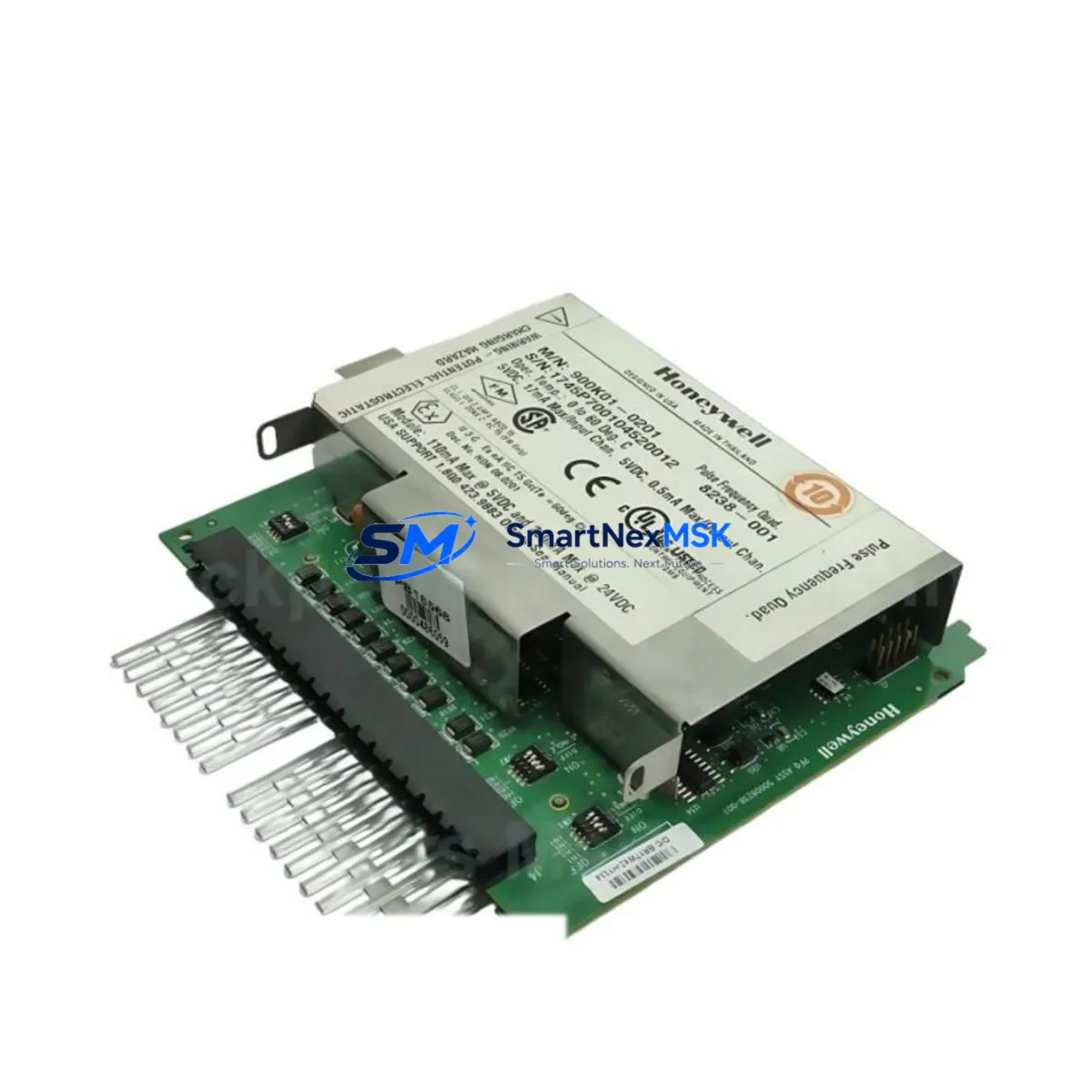
Honeywell 900RTC-BA25 Retrofit-Ready RTP Cable for HC900 Control Systems
The Honeywell 900RTC-BA25 is a DB25-interface Remote Termination Panel (RTP) cable engineered for the HC900 Hybrid Controller platform. As legacy distributed control systems age and OEM support windows close, the 900RTC-BA25 has become a critical retrofit component for engineers tasked with extending the operational life of existing HC900-based control cabinets without a full platform migration. Whether you are replacing a failed cable assembly, upgrading a deteriorated wiring harness, or re-commissioning a mothballed control panel, this cable provides a direct, pin-compatible drop-in solution that preserves your existing I/O mapping and analog signal integrity.
The 900RTC-BA25 connects HC900 analog output modules — typically the 900A0-0001 or 900A0-0002 series — to field-side Remote Termination Panels, routing up to eight channels of 4–20 mA or 0–10 V DC analog output signals through a shielded, impedance-matched cable assembly. The DB25 male connector mates directly with the RTP backplane socket, eliminating the need for field re-termination and dramatically reducing the risk of wiring errors during a hot-swap replacement. Cable shielding is grounded at the module end to suppress common-mode noise in electrically noisy industrial environments such as motor control centers, variable frequency drive cabinets, and high-current bus systems.
Before installing the 900RTC-BA25 in a retrofit scenario, engineers should verify several key parameters. First, confirm that the target HC900 chassis — whether a 4-slot, 8-slot, or 12-slot rack — has sufficient power supply headroom from the 900P01-0001 or 900P02-0001 power supply modules to support the analog output load after adding or replacing modules. Second, inspect the RTP backplane for bent or corroded DB25 pins, as a damaged socket will cause intermittent signal faults that are difficult to distinguish from field-device failures. Third, review the HC900 Designer configuration file to confirm that the analog output channel addresses assigned in the program logic match the physical slot and channel positions of the replacement module. A mismatch between the configured module address and the physical rack position will cause the HC900 controller to flag a hardware fault and suppress output signals.
In systems where the HC900 communicates with a Honeywell Experion PKS or a third-party SCADA platform via Modbus TCP or EtherNet/IP, replacing an analog output module and its associated RTP cable requires a communications link verification step. After the physical swap, confirm that the OPC server or Modbus polling table still maps correctly to the output register addresses. If the system uses a 900CS-0001 communication module for peer-to-peer data exchange between HC900 nodes, verify that the peer table has not been disrupted by the maintenance event. HMI faceplates that display analog output setpoints and feedback values should be tested in simulation mode before returning the loop to automatic control.
For control cabinets undergoing a broader modernization — for example, migrating from a legacy HC900 rack to a newer Honeywell ControlEdge HC900 or integrating additional I/O capacity through 900XTD-0001 I/O expansion modules — the 900RTC-BA25 remains compatible with the existing RTP infrastructure, allowing engineers to phase the upgrade without replacing the entire field wiring harness. This phased approach is particularly valuable in continuous-process industries where planned downtime windows are measured in hours, not days.
Upgrade Compatibility Table
| Parameter | Detail |
|---|---|
| SKU / Part Number | 900RTC-BA25 |
| Compatible Platform | Honeywell HC900 Hybrid Controller Series |
| Connector Interface | DB25 Male (RTP Backplane) |
| Signal Type | Analog Output — 4–20 mA / 0–10 V DC |
| Compatible Modules | 900A0-0001, 900A0-0002 Analog Output Modules |
| Compatible Racks | HC900 4-Slot, 8-Slot, 12-Slot Chassis |
| Installation Type | Direct Drop-In Replacement — No Field Re-Termination Required |
| Communication Compatibility | Modbus TCP, EtherNet/IP, Peer-to-Peer (via 900CS-0001) |
| Retrofit Recommendation | Verify power supply headroom, DB25 pin condition, and channel address mapping before installation |
| Commissioning Note | Test HMI faceplates and SCADA register mapping after replacement |
| Warranty | 12 Months from Date of Shipment |
Retrofit Planning for Existing Automation Systems
A successful HC900 retrofit begins with a thorough audit of the existing control cabinet. Start by documenting the current rack configuration: record the slot positions of all installed modules, including the 900C71-0243 or 900C72-0243 CPU modules, any 900A0-0001 analog output modules, 900DI-0460 digital input modules, 900DO-0460 digital output modules, and the 900P01-0001 power supply. Photograph the existing RTP cable routing before disconnection to preserve the as-built wiring record.
When the 900RTC-BA25 is being replaced as part of a broader I/O expansion — for example, adding a 900XTD-0001 remote I/O expansion module to extend the system’s reach to a satellite control panel — confirm that the HC900 Designer software version installed on the engineering workstation supports the firmware revision running on the CPU module. Firmware mismatches between the CPU and expansion modules are a common source of commissioning delays in retrofit projects. Similarly, if the project involves migrating from a serial Modbus RTU communications link to Ethernet-based Modbus TCP using a 900CS-0001 communications module, the IP address scheme and polling intervals must be reconfigured in both the HC900 Designer project file and the SCADA or DCS host system before the new cable assembly is energized.
For projects that include HMI panel upgrades — replacing an aging Honeywell Station or third-party operator panel with a modern touchscreen HMI — the analog output channel tags referenced in the HMI project must be re-mapped to match the updated HC900 configuration. This step is frequently overlooked during fast-track retrofits and can result in operators seeing stale or incorrect process values on the new display. A pre-commissioning simulation run using the HC900 Designer’s offline emulation mode, with the 900RTC-BA25 connected but the field devices isolated, allows the engineering team to verify tag mapping and alarm setpoints before live process fluids or electrical loads are connected.
Downtime Control During System Migration
Minimizing unplanned downtime during an HC900 cable replacement or module swap requires a structured pre-outage preparation protocol. Before the maintenance window opens, download and archive the current HC900 Designer project file from the CPU module using the online upload function. Store the backup on both the engineering workstation and a removable drive kept in the control room. This ensures that if the replacement procedure encounters an unexpected fault — such as a corrupted module configuration or a rack communication error — the original program logic can be restored within minutes rather than hours.
During the physical swap of the 900RTC-BA25, place all affected analog output loops in manual mode at the DCS or SCADA level before disconnecting the cable. This prevents the control system from driving field actuators — control valves, variable speed drives, or positioners — to their fail-safe positions due to a loss of the 4–20 mA signal during the cable change. After the new cable is seated and the DB25 connector is secured, restore power to the rack and allow the HC900 CPU to complete its self-diagnostic cycle before returning loops to automatic. Monitor the HC900 diagnostic display and the SCADA alarm summary for any hardware fault codes that indicate a module address conflict or a power supply overload condition. A clean restart with no active faults confirms that the 900RTC-BA25 replacement has been completed successfully and that the system is ready for loop testing.
Retrofit Support FAQ
Q: Is the 900RTC-BA25 a direct replacement for the original Honeywell cable, or does it require any wiring modifications?
A: The 900RTC-BA25 is a pin-compatible, direct drop-in replacement for the original Honeywell HC900 RTP cable. No field wiring modifications are required. The DB25 connector mates directly with the RTP backplane socket, and the cable shield is pre-terminated at the module end. Verify that the DB25 socket on the RTP backplane is free of bent pins or corrosion before installation.
Q: What commissioning steps are required after replacing the 900RTC-BA25 in a live HC900 system?
A: After physical installation, power up the rack and confirm that the HC900 CPU module completes its self-diagnostic cycle without hardware fault codes. Verify that all analog output channels are reporting correctly in the HC900 Designer online view. Place each affected loop in manual mode, apply a known output signal, and confirm the correct mA value at the field device terminals using a calibrated loop calibrator. Return loops to automatic only after all channels have been verified.
Q: Can the 900RTC-BA25 be used with both the 900A0-0001 and 900A0-0002 analog output modules?
A: Yes. The 900RTC-BA25 is compatible with both the 900A0-0001 (8-channel, 4–20 mA) and 900A0-0002 (8-channel, 0–10 V DC) analog output modules. Confirm the signal type configuration in the HC900 Designer channel setup matches the field device input specification before energizing the loop.
Q: What warranty coverage is provided, and what does it include?
A: All 900RTC-BA25 units supplied by SMARTNEXMSK carry a 12-month warranty from the date of shipment. The warranty covers manufacturing defects in materials and workmanship, including connector integrity, cable shielding continuity, and pin contact resistance. Each unit undergoes pre-shipment functional testing. Warranty claims are supported by our technical team at [email protected].
© 2026 SMARTNEXMSK. All rights reserved.
Original Source: https://smartnexmsk.com
Contact: [email protected] | +86 18259474341



