
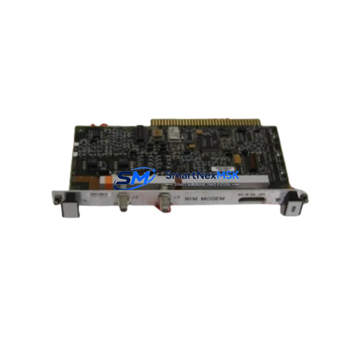
Honeywell FC-DO-1224 Retrofit-Ready Digital Output Module for Safety Manager FS Control Systems
The Honeywell FC-DO-1224 is a 24 VDC Digital Output Module engineered for direct integration into the Safety Manager FS (Fail-Safe) platform — one of the most widely deployed safety instrumented systems (SIS) in the process automation industry. As legacy Safety Manager cabinets approach end-of-life and spare-parts availability tightens, the FC-DO-1224 has become a critical retrofit component for engineers tasked with extending system lifespan, replacing discontinued output cards, and maintaining SIL 2/SIL 3 loop integrity without a full system overhaul.
Whether you are replacing a failed output module mid-campaign, upgrading an aging control cabinet, or migrating from an earlier Safety Manager generation, the FC-DO-1224 slots directly into the existing FS Series backplane without requiring chassis replacement or firmware re-engineering. Its 24-channel digital output architecture supports both energize-to-trip (ETT) and de-energize-to-trip (DETT) configurations, making it adaptable to a wide range of field device wiring schemes already in place on your plant floor.
Before installation, engineers should verify the following against the existing system documentation: available power budget on the FC-PSU-2410 or FC-PSU-2420 power supply module, terminal block wiring assignments on the existing I/O marshalling panel, backplane slot addressing and module configuration within the Safety Manager engineering workstation, and any active SIL verification reports that reference the outgoing module’s diagnostic coverage figures. Updating the module address in the Safety Manager configuration tool and performing a full I/O checkout prior to hot-cutover is strongly recommended to avoid nuisance trips.
For sites running the FC-SDO-0824 or FC-SDO-1624 in adjacent slots, the FC-DO-1224 can be introduced into the same rack without disrupting neighboring module communication. The Safety Manager FS backplane uses a deterministic communication bus, and module insertion follows a defined slot-assignment protocol managed through the Honeywell Safety Manager Engineering Studio. Ensure that the module’s hardware revision is compatible with the firmware version loaded on the FC-CPU-0702 or FC-CPU-0714 safety controller before commissioning.
In retrofit projects involving communication protocol migration — for example, transitioning from legacy Modbus RTU links to FOUNDATION Fieldbus or PROFIBUS DP — the FC-DO-1224 remains protocol-agnostic at the I/O level, with all protocol handling managed upstream by the FC-COM-PBDP or FC-COM-FF communication modules. This separation of concerns simplifies the migration path and allows output module replacement to proceed independently of the communication layer upgrade schedule.
For control cabinet upgrades that also involve HMI panel replacement or SCADA screen migration, confirm that all FC-DO-1224 channel tags are correctly mapped in the Experion PKS or third-party DCS historian before switching over. Mismatched tag names between the outgoing module configuration and the new HMI faceplate are a common source of commissioning delays. A pre-cutover tag audit against the existing FC-AI-1620 and FC-DI-1624 module configurations in the same cabinet is advisable.
All units supplied by SMARTNEXMSK are sourced from authorized distribution channels, subject to incoming inspection, and shipped with a 12-month warranty covering manufacturing defects and functional failures under normal operating conditions. Each FC-DO-1224 is tested for output channel continuity, diagnostic self-test response, and backplane connector integrity prior to dispatch. Expedited shipping is available for emergency breakdown situations, with same-day dispatch for in-stock units confirmed before 14:00 CST.
Upgrade Compatibility Table
| Parameter | FC-DO-1224 (This Unit) | Notes / Retrofit Guidance |
|---|---|---|
| Output Channels | 24 x 24 VDC Digital Output | Verify field device load current does not exceed per-channel rating |
| Backplane Interface | Safety Manager FS Series Backplane | Direct drop-in; no chassis modification required |
| Compatible Controllers | FC-CPU-0702, FC-CPU-0714 | Confirm firmware revision compatibility before commissioning |
| Trip Logic | ETT / DETT configurable | Match existing field wiring scheme; document in SIL verification record |
| Communication Bus | Internal FS backplane bus | Protocol-agnostic at I/O level; upstream handled by FC-COM-PBDP / FC-COM-FF |
| Power Supply Compatibility | FC-PSU-2410, FC-PSU-2420 | Verify available power budget before adding module to existing rack |
| Installation Method | Hot-swap capable (per SM engineering guidelines) | Follow Safety Manager hot-insertion procedure; confirm with site safety authority |
| SIL Rating | SIL 2 / SIL 3 loop compatible | Update SIL verification report after module replacement |
| Warranty | 12 Months | Covers manufacturing defects and functional failures under normal operation |
| Origin | Germany | Sourced from authorized distribution; incoming inspection performed |
Retrofit Planning for Existing Automation Systems
A successful FC-DO-1224 retrofit begins well before the module arrives on site. Start by pulling the existing rack layout drawing to confirm the target slot number and verify that the adjacent FC-DI-1624 digital input modules and FC-AI-1620 analog input modules are not sharing a power segment that is already at capacity. Cross-reference the terminal block assignments on the marshalling cabinet against the I/O list in the Safety Manager project database — any discrepancy between the wiring schedule and the configured channel assignments must be resolved before the new module is inserted.
If the retrofit is part of a broader cabinet upgrade that includes replacing the FC-PSU-2410 power supply or adding a redundant FC-PSU-2420, sequence the power work first so that the new module is commissioned against a known-good power rail. For sites also upgrading the FC-COM-PBDP communication module to support a new PROFIBUS DP segment, coordinate the communication cutover separately from the I/O module swap to isolate fault domains during commissioning.
Sites migrating from older Safety Manager generations that used the FC-SDO-0824 (8-channel) or FC-SDO-1624 (16-channel) output modules should note that the FC-DO-1224 provides 24 channels, which may require updating the module configuration in Safety Manager Engineering Studio and re-mapping any spare channels in the HMI tag database. The FC-TERM-DO24 terminal assembly is the recommended field wiring interface for the FC-DO-1224 and should be ordered alongside the module if the existing terminal assembly is not compatible.
For projects that also involve replacing the FC-CPU-0702 safety controller with the newer FC-CPU-0714, perform the controller upgrade and validation first, then introduce the FC-DO-1224 into the validated system. This sequencing ensures that any firmware-level diagnostic changes introduced by the new controller are captured in the module’s self-test results from day one of operation.
Downtime Control During System Migration
Minimizing unplanned downtime during a Safety Manager FS module replacement requires a structured pre-outage preparation protocol. Before the maintenance window opens, export the full Safety Manager project from Engineering Studio and archive it to a secure offline location — this preserves the original program logic, module addressing, and I/O configuration as a recovery baseline. Confirm that the FC-DO-1224 replacement unit has passed pre-shipment functional testing and that the 12-month warranty documentation is on file before the outage begins.
During the cutover window, follow the Safety Manager hot-insertion procedure if the site safety authority has approved online module replacement. For sites requiring a cold swap, coordinate with the control room to place the affected safety loops in manual bypass mode using the approved bypass management procedure, and notify the distributed control system (DCS) operator to suppress any alarms associated with the FC-DO-1224 output channels during the swap interval. After module insertion, allow the Safety Manager to complete its automatic self-test cycle before releasing the bypassed loops back to automatic control.
Post-cutover, perform a channel-by-channel output verification against the field device list, confirm that all HMI status indicators reflect the correct module state, and update the maintenance record with the new module serial number and installation date. The 12-month warranty period begins from the date of commissioning as documented in the site maintenance log.
Retrofit Support FAQ
Q: Is the FC-DO-1224 a direct drop-in replacement for older Safety Manager digital output modules?
A: Yes, the FC-DO-1224 is designed for direct backplane compatibility with the Safety Manager FS Series chassis. For sites replacing FC-SDO-0824 or FC-SDO-1624 modules, a configuration update in Safety Manager Engineering Studio is required to reflect the increased channel count. No physical chassis modification is needed.
Q: What wiring changes are required when installing the FC-DO-1224?
A: If the existing terminal assembly (FC-TERM-DO24) is already installed, no field wiring changes are required. If the site is upgrading from an 8- or 16-channel output module, additional terminal positions will need to be wired for the new channels. Always verify terminal block torque specifications and conductor sizing against the Safety Manager installation manual before energizing.
Q: How is the FC-DO-1224 tested before shipment?
A: Each unit undergoes incoming inspection covering output channel continuity, diagnostic self-test response, and backplane connector integrity. Units are shipped with a test report and are covered by a 12-month warranty from the date of commissioning. Emergency breakdown units can be dispatched same-day for in-stock orders confirmed before 14:00 CST.
Q: Does replacing the FC-DO-1224 require updating the SIL verification documentation?
A: Yes. Any safety instrumented system module replacement that affects the hardware configuration of a SIL-rated loop must be reflected in the updated SIL verification report. Consult your functional safety engineer to confirm that the replacement module’s diagnostic coverage and safe failure fraction figures are consistent with the original SIL claim for the affected loops.
© 2026 SMARTNEXMSK. All rights reserved.
Original Source: https://smartnexmsk.com
Contact: [email protected] | +86 18259474341



