
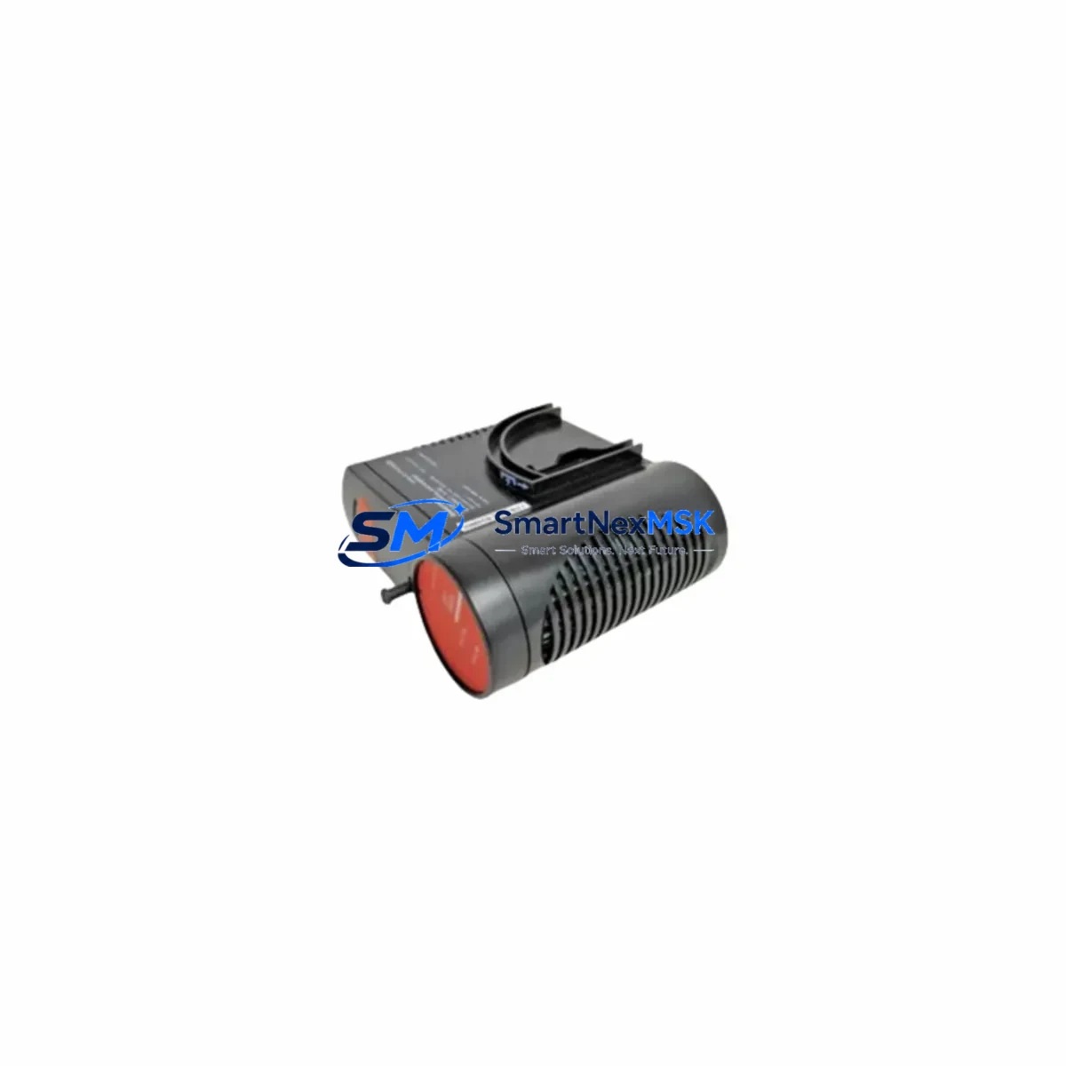
Honeywell FC-PDIO01 Retrofit-Ready Safety DIO Module for Safety Manager SC Control Systems
The Honeywell FC-PDIO01 is a Safety Digital Input/Output module designed for the Safety Manager SC platform — one of Honeywell’s most widely deployed safety instrumented systems across oil & gas, petrochemical, power generation, and process manufacturing industries. As legacy Safety Manager installations approach end-of-life or require capacity expansion, the FC-PDIO01 remains a critical retrofit component for engineers tasked with maintaining SIL2 and SIL3 functional safety integrity without full system replacement.
This module provides mixed digital I/O capability within the Safety Manager SC chassis, supporting both input diagnostics and output drive functions in a single slot. When replacing a failed or obsolete FC-PDIO01, engineers must verify the backplane slot assignment, confirm the module address configuration within the Safety Builder engineering tool, and validate that the existing I/O mapping in the safety application program remains intact. Any mismatch between the physical slot address and the software-defined channel assignment can trigger a safety system fault and initiate an unplanned shutdown.
Before installation, confirm that the FC-PDIO01 power draw is within the capacity of the installed FC-PSU power supply module. Safety Manager SC cabinets typically house multiple I/O modules alongside the FC-SDO16 digital output modules and FC-SDI16 digital input modules, and cumulative current draw must be evaluated against the chassis power budget. If the existing power supply is already near capacity, a supplementary FC-PSU unit may be required before the retrofit can proceed safely.
Terminal wiring for the FC-PDIO01 follows the standard Safety Manager SC field termination convention. Engineers should reference the original loop drawings and confirm that field device wiring — including NAMUR sensors, solenoid valve drivers, and emergency shutdown (ESD) actuators — is correctly mapped to the module’s terminal block. Where the original wiring used a marshalling cabinet with cross-wiring to the I/O module, the retrofit process should include a point-to-point continuity check before powering up the replacement module.
Communication between the FC-PDIO01 and the Safety Manager SC controller module (FC-SMSC01 or FC-SMSC02) is handled internally via the backplane bus. No external communication cable is required for standard I/O operation. However, if the system also includes a Fault Tolerant Ethernet (FTE) network for integration with Experion PKS or a third-party DCS, engineers should verify that the FTE switch configuration and node addressing remain consistent after the module swap. Changes to the I/O module inventory can sometimes trigger a configuration mismatch alarm in the Experion Station HMI display, requiring a controlled download of the updated hardware configuration.
For sites running Safety Manager SC alongside a Honeywell Experion PKS C300 controller or a legacy TDC 3000 system, the FC-PDIO01 retrofit is typically part of a broader I/O modernization effort. In these environments, it is common to simultaneously address aging FC-TCCH thermocouple input modules, FC-AI16 analog input modules, and FC-AO08 analog output modules that share the same chassis. Coordinating these replacements during a planned turnaround minimizes the number of separate maintenance windows and reduces cumulative downtime exposure.
Every FC-PDIO01 unit supplied by SMARTNEXMSK is pre-tested under simulated load conditions prior to shipment. Functional verification includes channel-by-channel I/O response testing, diagnostic self-test confirmation, and backplane communication handshake validation. Units are shipped with full documentation and are covered by a 12-month warranty against manufacturing defects and functional failure. Expedited shipping is available for emergency breakdown situations where production continuity is at risk.
Upgrade Compatibility Table
| Parameter | Details |
|---|---|
| Compatible Platform | Honeywell Safety Manager SC (FC-SMSC01, FC-SMSC02) |
| Module Type | Safety Digital I/O (Mixed DIO) |
| Safety Integrity Level | SIL2 / SIL3 capable |
| Backplane Interface | Safety Manager SC standard backplane bus |
| Installation Slot | Any standard I/O slot in SM SC chassis |
| Power Requirement | Supplied via backplane from FC-PSU; verify chassis power budget |
| Terminal Wiring | Standard SM SC field termination; confirm loop drawings before swap |
| Communication Link | Internal backplane; FTE network integration via Experion PKS |
| Engineering Tool | Safety Builder (address and channel mapping validation required) |
| Replacement Recommendation | Direct drop-in replacement; verify slot address and I/O mapping |
| Commissioning Focus | Channel diagnostics, self-test confirmation, HMI alarm clearance |
| Warranty | 12-Month Warranty — functional and manufacturing defect coverage |
Retrofit Planning for Existing Automation Systems
A successful FC-PDIO01 retrofit begins well before the module arrives on site. The engineering team should extract the current hardware configuration from Safety Builder and document every occupied slot in the Safety Manager SC chassis. This snapshot serves as the baseline for post-replacement verification and ensures that the FC-SMSC01 or FC-SMSC02 controller module does not detect an unexpected hardware change during the controlled restart sequence.
In cabinets where the FC-PDIO01 shares a chassis with FC-SDI16 digital input modules and FC-SDO16 digital output modules, the slot numbering must be carefully preserved. Safety Builder assigns logical channel addresses based on physical slot position, and any deviation — even a temporary relocation during maintenance — can corrupt the I/O mapping and require a full application download to restore correct operation. If the chassis also houses FC-AI16 analog input modules or FC-AO08 analog output modules serving critical process measurements, those channels should be placed in manual override or bypass mode in the Experion PKS HMI before the I/O module swap begins.
Where the Safety Manager SC system communicates with a Honeywell Experion PKS C300 controller via the FTE network, the system integrator should confirm that the Experion Station HMI graphics referencing FC-PDIO01 channel tags are not in alarm suppression mode during the retrofit window. After the replacement module is seated and powered, a channel-by-channel functional test should be performed from the HMI to confirm that all digital inputs and outputs are responding correctly before the bypass is lifted and the safety function is restored to automatic mode.
For older installations that include a Honeywell TDC 3000 Data Hiway interface or a legacy Universal Control Network (UCN) segment, the retrofit team should also verify that the safety system gateway configuration has not been affected by the module replacement. In some multi-system architectures, the FC-PDIO01 channels feed interlock logic that is also referenced by the Basic Process Control System (BPCS), and any temporary loss of signal during the swap must be managed through pre-agreed cause-and-effect bypass procedures documented in the Management of Change (MOC) package.
Programming cable access to the Safety Manager SC engineering port — typically via a standard Ethernet connection to the FC-SMSC controller — should be confirmed before the maintenance window begins. Having the Safety Builder project file open and ready for a controlled download eliminates delays if a configuration mismatch is detected after the module swap. SMARTNEXMSK recommends that a qualified functional safety engineer (TÜV-certified or equivalent) supervise the commissioning of any SIL-rated I/O module replacement to ensure compliance with IEC 61511 proof test and validation requirements.
Downtime Control During System Migration
Minimizing downtime during an FC-PDIO01 replacement requires a structured approach that protects the original safety application logic while maintaining field control continuity. The recommended sequence begins with a formal bypass authorization — placing the affected safety function into a defined inhibit state within Safety Builder and documenting the bypass in the site’s safety management system. This step ensures that the process remains under controlled supervision even while the I/O module is physically absent from the chassis.
The physical swap itself is typically completed in under 15 minutes for a trained technician familiar with the Safety Manager SC chassis. The FC-PDIO01 is a hot-swap-capable module in most SM SC configurations, meaning the chassis does not need to be fully de-energized for the replacement — however, site-specific safety procedures and local electrical safety regulations always take precedence over general guidance. After seating the replacement module, Safety Builder will perform an automatic hardware recognition sequence, and the engineer should confirm that the module firmware version is compatible with the current application project before proceeding.
Once the module is recognized and the channel diagnostics confirm healthy status, the bypass can be lifted in a controlled sequence — restoring each safety function individually and verifying the corresponding HMI indication before moving to the next channel. This incremental restoration approach prevents a simultaneous surge of alarm activations that could overwhelm the operator and mask a genuine process deviation. The entire commissioning sequence, from bypass authorization to full restoration, can typically be completed within a two-hour planned maintenance window when the replacement module has been pre-tested and all documentation is prepared in advance.
SMARTNEXMSK ships every FC-PDIO01 with a pre-test report confirming channel-level functional verification, reducing the risk of discovering a defective unit during the maintenance window. For critical applications where a backup module is required, we maintain in-stock inventory to support same-day or next-day dispatch, ensuring that emergency breakdown situations do not extend into multi-day outages.
Retrofit Support FAQ
Q: Is the FC-PDIO01 a direct drop-in replacement for an existing Safety Manager SC DIO module?
A: Yes. The FC-PDIO01 is designed as a direct slot-compatible replacement within the Safety Manager SC chassis. No hardware modifications are required. However, engineers must verify the slot address assignment in Safety Builder and confirm that the I/O channel mapping in the safety application program matches the physical wiring before restoring the safety function to automatic mode.
Q: What wiring checks are required before installing the replacement FC-PDIO01?
A: Prior to installation, perform a point-to-point continuity check on all field wiring connected to the module’s terminal block. Confirm that NAMUR sensor loops, solenoid valve circuits, and ESD actuator wiring are correctly identified against the original loop drawings. Verify that no field device has been rewired or relabeled since the original commissioning documentation was produced.
Q: How is compatibility with SIL2 and SIL3 applications verified after replacement?
A: After installation, Safety Builder will perform an automatic diagnostic self-test on the FC-PDIO01. The engineer should confirm that all channel diagnostics return a healthy status and that no fault codes are present in the Safety Manager SC diagnostic log. For SIL3 applications, a formal proof test record should be completed in accordance with the site’s IEC 61511 safety lifecycle documentation, confirming that the replacement module meets the required diagnostic coverage and safe failure fraction.
Q: What does the 12-month warranty cover, and how is a warranty claim processed?
A: The 12-month warranty covers functional failure and manufacturing defects under normal operating conditions. If a unit fails within the warranty period, contact SMARTNEXMSK at [email protected] with the original order reference and a description of the fault. A replacement unit will be dispatched after fault confirmation, and the defective unit should be returned for inspection. Warranty claims are typically resolved within 5–7 business days from initial contact.
© 2026 SMARTNEXMSK. All rights reserved.
Original Source: https://smartnexmsk.com
Contact: [email protected] | +86 18259474341



