
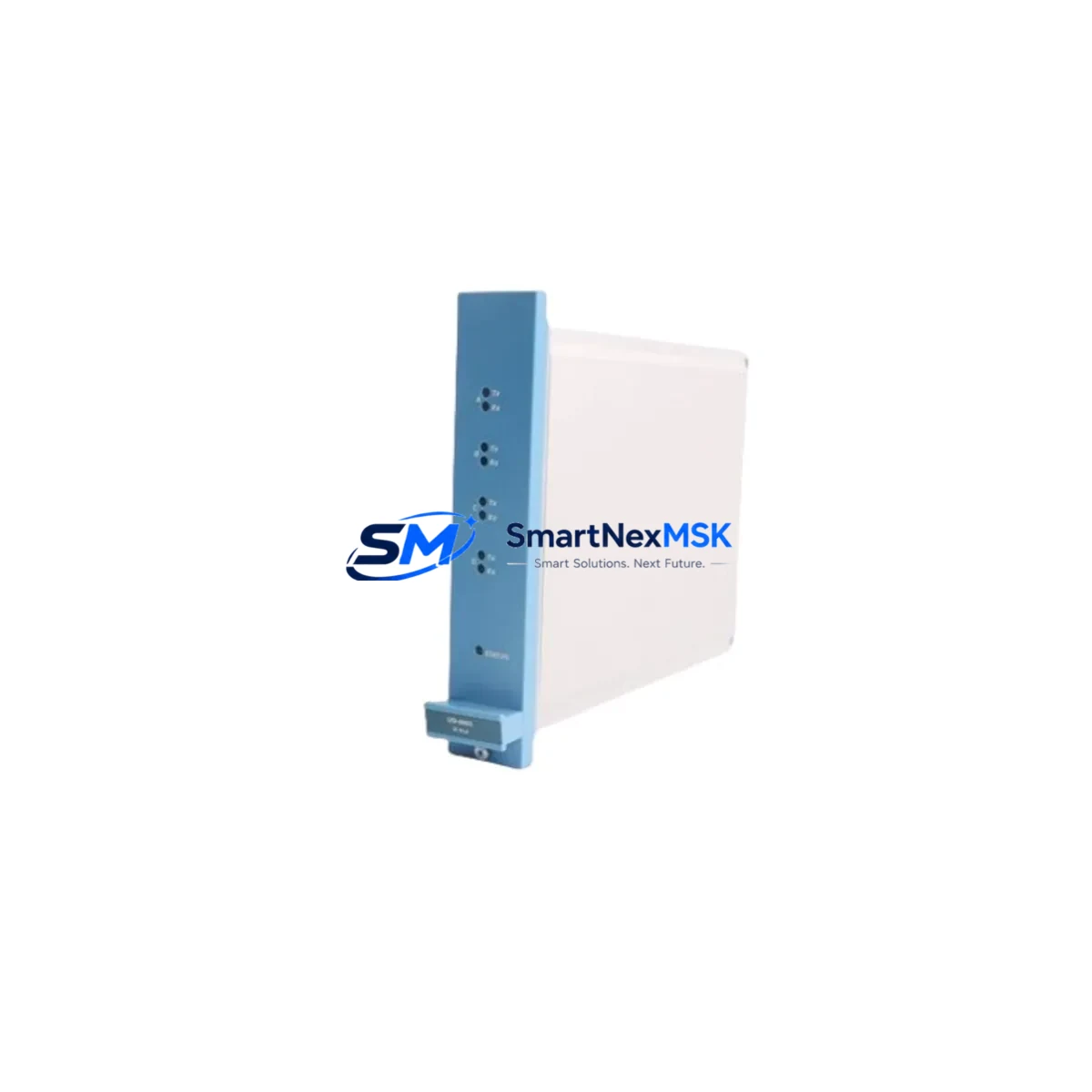
Honeywell FC-USI-0002 Retrofit-Ready Safety Interface Module for FC Safety Series Control Systems
The Honeywell FC-USI-0002 V1.0 is a Safety Interface Module designed for integration within the Honeywell FC Safety Series control platform. As legacy safety systems approach end-of-life or require modernization, the FC-USI-0002 serves as a critical bridge component — enabling engineers to retrofit aging safety architectures without full system replacement. Whether you are replacing a failed unit, upgrading a discontinued module, or migrating from an older Honeywell safety controller generation, the FC-USI-0002 provides the electrical compatibility, communication integrity, and functional safety compliance required for seamless transition.
This module is engineered to interface with the FC Safety Controller backplane, supporting direct installation into existing rack assemblies without mechanical modification. Engineers working on brownfield upgrades will find that the FC-USI-0002 maintains backward compatibility with established I/O wiring schemes, reducing rewiring time and minimizing exposure to human error during cutover. Before installation, it is essential to verify the backplane slot assignment, confirm the module address configuration matches the original unit, and review the safety program logic within the FC Safety Controller to ensure no function block references require revision.
Upgrade Compatibility Table
| Parameter | FC-USI-0002 V1.0 Specification |
|---|---|
| Module Type | Safety Interface Module (USI) |
| Compatible Platform | Honeywell FC Safety Series Control System |
| Backplane Interface | FC Series rack backplane connector (direct slot insertion) |
| Communication Protocol | FC Safety internal bus; compatible with FC Safety Controller communication layer |
| Installation Requirement | Standard FC rack; no mechanical modification required |
| Replacement Compatibility | Direct replacement for FC-USI-0002 V1.0; verify firmware revision before swap |
| Wiring Adaptation | Existing terminal wiring retained; confirm terminal block pinout against original drawing |
| Module Address | Configured via FC Safety Controller engineering station; must match original slot assignment |
| Commissioning Requirement | Safety function validation test required post-installation per IEC 61508 / SIL procedures |
| Warranty | 12-Month Warranty — covers manufacturing defects and functional failure under normal operating conditions |
Retrofit Planning for Existing Automation Systems
Successful integration of the FC-USI-0002 into an existing safety system requires a structured retrofit plan that accounts for the full scope of interdependent components. In a typical FC Safety Series control cabinet, the FC-USI-0002 operates alongside the FC-SDO-0824 safety digital output module and the FC-SDI-1616 safety digital input module, both of which share the same backplane and must be confirmed operational before and after the USI swap. The FC Safety Controller itself — often an FC-SCPU-0101 or equivalent CPU module — holds the safety program and must remain powered and in run mode during the pre-swap diagnostic phase to capture any active fault codes associated with the failing USI module.
Power supply integrity is a prerequisite for any retrofit. The FC Safety Series rack is typically powered by a dedicated FC-PSU-2410 or equivalent 24 VDC safety-rated power supply module. Before removing the FC-USI-0002, engineers should measure rail voltage at the backplane connector and confirm it falls within the module’s rated input tolerance. Insufficient power headroom — particularly in cabinets where additional I/O modules have been added over time — can cause intermittent faults that mimic USI hardware failure.
Communication continuity is another key consideration. In systems where the FC Safety Controller communicates upstream to a DCS or SCADA platform via Modbus TCP, PROFIBUS DP, or Ethernet/IP, the communication module — such as an FC-COM-ETH01 or equivalent gateway card — must remain active throughout the swap to avoid triggering a communication loss alarm at the supervisory level. Where possible, coordinate the cutover window with the control room operator to place the affected safety loop in bypass mode per the site’s Management of Change (MOC) procedure.
For systems that include an HMI panel — typically a Honeywell-compatible operator interface or a third-party panel running a mirrored safety status display — verify that the HMI tag database references the FC-USI-0002 by slot address rather than by module serial number. This distinction is critical: slot-addressed HMI configurations will automatically recognize the replacement module without requiring a tag remap, while serial-number-addressed configurations will require an HMI project update and re-download before the new module is visible on the operator screen.
Where the retrofit involves migrating from an older generation of Honeywell safety hardware — such as the legacy FSC (Fail Safe Controller) platform — to the FC Safety Series, the FC-USI-0002 plays a role in the I/O marshalling layer. In these migration projects, a terminal block adapter or field wiring adapter panel is often used to preserve existing field cable terminations while adapting to the FC rack’s connector format. Confirm that the adapter panel’s signal routing matches the new module’s channel assignment before energizing the system.
Downtime Control During System Migration
Minimizing unplanned downtime during a safety system retrofit is a primary engineering objective. For the FC-USI-0002 replacement, the recommended approach is a hot-standby swap sequence where operationally feasible: place the affected safety function in a defined safe state, document all active I/O states and interlock statuses, remove the failed module, insert the replacement FC-USI-0002, and restore the safety function only after completing the mandatory post-installation validation test.
Before the physical swap, export the current FC Safety Controller program to a backup file using the FC Safety Engineering Station software. This backup preserves the full function block diagram, safety loop configuration, module address map, and interlock logic. If the replacement module requires a firmware update to match the controller’s expected version, perform the update offline using the engineering station before rack insertion — this eliminates the risk of a firmware mismatch fault during the live cutover.
For sites operating under a continuous process environment where even brief safety loop interruptions are unacceptable, consider deploying a temporary bypass relay panel to maintain hardwired safety circuit continuity during the module swap window. This approach is common in petrochemical, power generation, and pharmaceutical applications where the FC Safety Series is used to protect critical process equipment. Document the bypass activation and deactivation in the site’s safety management system and obtain the required authorization signatures before proceeding.
Post-installation, conduct a full proof test of each safety function associated with the FC-USI-0002 channel assignments. Record the test results in the site’s safety instrumented system (SIS) maintenance log. This documentation is required for IEC 61511 compliance and will be requested during the next functional safety audit. All units supplied by SMARTNEXMSK are pre-tested prior to shipment, with test records available upon request.
Retrofit Support FAQ
Q1: Is the FC-USI-0002 V1.0 a direct drop-in replacement for the original Honeywell module?
Yes. The FC-USI-0002 V1.0 is designed as a form-fit-function replacement for the original Honeywell FC-USI-0002. The backplane connector, slot dimensions, and module address configuration are identical. However, engineers should verify the firmware revision level of the replacement module against the FC Safety Controller’s compatibility matrix before installation. If a firmware update is required, it can be performed using the FC Safety Engineering Station prior to rack insertion.
Q2: What wiring changes are required when replacing the FC-USI-0002?
In most cases, no wiring changes are required. The FC-USI-0002 uses the same terminal block pinout as the original module, allowing existing field cables to be reconnected directly. Before reconnection, inspect each terminal for signs of corrosion, loose strands, or insulation damage. Re-torque all terminals to the manufacturer’s specified value. If the original installation used a removable terminal block, the entire block can be transferred to the replacement module without disturbing individual wire terminations.
Q3: How do I verify communication compatibility after installing the replacement module?
After installation, power up the FC Safety Controller and observe the module status indicators on the FC-USI-0002 front panel. A solid green status LED confirms successful backplane communication and module initialization. Use the FC Safety Engineering Station to perform an online module scan and verify that the replacement module appears at the correct slot address with the expected I/O channel count. If the module reports a communication fault, check the backplane connector seating, verify the slot address configuration, and confirm that the FC Safety Controller firmware version supports the installed module revision.
Q4: What does the 12-month warranty cover, and what is the return process?
All FC-USI-0002 modules supplied by SMARTNEXMSK are covered by a 12-month warranty from the date of shipment. The warranty covers manufacturing defects, component failure under normal operating conditions, and functional non-conformance to the published specification. It does not cover damage resulting from incorrect installation, overvoltage, reverse polarity, or unauthorized modification. To initiate a warranty claim, contact [email protected] with the order number, module serial number, and a description of the observed fault. Replacement units are dispatched within 3 business days of claim approval.
© 2026 SMARTNEXMSK. All rights reserved.
Original Source: https://smartnexmsk.com
Contact: [email protected] | +86 18259474341



