
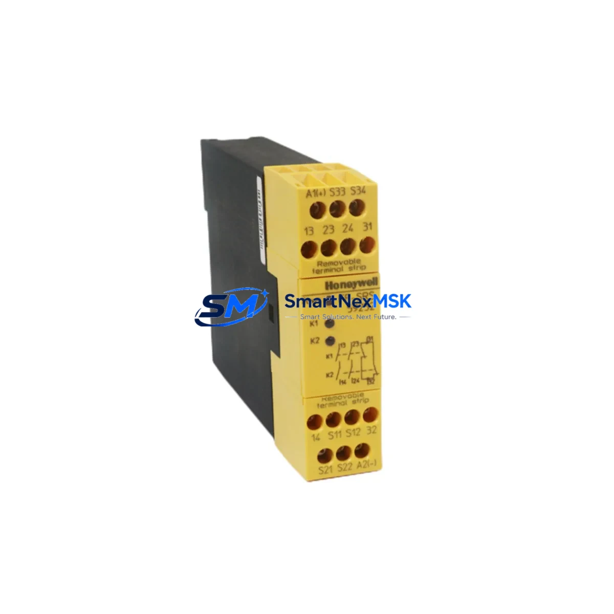
Honeywell FF-SRS59252 Maintenance-Ready Spare for Safety Manager Automation
The Honeywell FF-SRS59252 is an original safety relay module designed for the Honeywell Safety Manager Series — a widely deployed safety instrumented system (SIS) platform in oil & gas, chemical processing, power generation, and heavy industrial facilities. As a maintenance-ready spare, the FF-SRS59252 is engineered to support rapid field replacement, minimize unplanned downtime, and sustain the functional safety integrity of your SIL-rated control architecture.
For maintenance engineers managing aging SIS infrastructure, having a verified, tested FF-SRS59252 on the shelf is not optional — it is a core element of any credible spare parts strategy. Emergency shutdowns triggered by a failed safety relay module can cascade into extended production halts, regulatory non-compliance, and costly restart procedures. Stocking this module as a ready-to-deploy spare eliminates that risk.
Spare Maintenance Table
| Parameter | Specification |
|---|---|
| Part Number | FF-SRS59252 |
| Brand | Honeywell |
| Series | Safety Manager (SM) |
| Module Type | Safety Relay Output Module |
| Safety Integrity Level | SIL 2 / SIL 3 capable (per IEC 61508) |
| Supply Voltage | 24 VDC (nominal) |
| Output Type | Relay contact output (safety-rated) |
| Compatibility | Honeywell Safety Manager SM Series chassis and backplane |
| Installation | Hot-swap capable (verify with system documentation); DIN-rail / rack-mount chassis |
| Operating Temperature | 0°C to +60°C |
| Certifications | TÜV, IEC 61508, IEC 61511 compliant |
| Weight | Approx. 220 g |
| Origin | USA |
| Condition | Original, new or refurbished-to-spec; tested before shipment |
| Warranty | 12 Months |
| Lead Time | In-stock: ships within 2 business days |
Maintenance Planning for Continuous Operation
When replacing the FF-SRS59252 in a Safety Manager cabinet, a disciplined maintenance engineer does not stop at the relay module itself. The surrounding electrical circuit and system architecture must be inspected concurrently to prevent repeat failures and ensure the safety loop is fully restored to its designed functional state.
Begin with the SM power supply module (such as the FF-PSU59x series) — a degraded or under-spec power supply is a leading cause of relay module faults and should be load-tested before the new FF-SRS59252 is commissioned. Inspect the FF-SDO59x digital output module in adjacent slots, as shared backplane power rails can propagate faults across modules. Verify the FF-SRM59x safety relay module variants in the same chassis for signs of contact wear or coil degradation.
On the field wiring side, inspect all terminal blocks and field wiring connectors on the I/O marshalling panel — corroded or loose terminals are a common root cause of intermittent relay faults that are misdiagnosed as module failures. Check the signal isolators on any 4–20 mA loops feeding the safety logic, particularly if the installation is in a high-EMI environment. Fuse holders and miniature circuit breakers (MCBs) protecting the relay output circuits should be tested for continuity and rated trip current.
For systems with Honeywell Safety Manager communication modules (e.g., FF-SCM59x), verify that the module firmware version is compatible with the replacement relay module and that the safety network (typically FOUNDATION Fieldbus or Modbus) is communicating without error flags after the swap. If the plant uses a Honeywell Experion PKS or Safety Builder configuration environment, confirm that the I/O assignment and safety function block mapping remain intact post-replacement.
Where the Safety Manager interfaces with a Honeywell HC900 hybrid controller or legacy TDC 3000 system for non-safety process control, inspect the inter-system hardwired trip signals and confirm relay contact ratings match the load. Finally, review the HMI alarm summary on the operator station — any latched safety alarms related to the FF-SRS59252 slot must be cleared and re-validated after the replacement is complete and the safety function proof-tested.
Site Replacement Workflow
Step 1 — Permit and Isolation: Obtain a valid work permit. Isolate the affected safety loop per your site Management of Change (MOC) and Permit to Work (PTW) procedures. Do not bypass the safety function without authorized inhibit documentation.
Step 2 — Module Identification: Confirm the slot address and module type via the Safety Builder configuration tool or the chassis label. Cross-reference the FF-SRS59252 part number on the module faceplate before removal.
Step 3 — Removal: If the system supports hot-swap for this module type (verify in the Safety Manager hardware manual), remove the module with the chassis powered. Otherwise, follow the controlled shutdown sequence. Retain the failed module for failure analysis.
Step 4 — Installation: Insert the replacement FF-SRS59252 into the correct slot. Ensure the module is fully seated on the backplane connector. Reconnect field wiring terminals and verify torque on all screw terminals.
Step 5 — Commissioning and Proof Test: Power up and confirm the module status LED indicates healthy operation. Execute a partial stroke or full proof test of the safety function per IEC 61511 requirements. Document the test result in your safety management system.
Step 6 — Return to Service: Remove any inhibits, confirm the safety loop is active, and update the maintenance record with the replacement date, module serial number, and proof test result.
This workflow is applicable whether you are replacing an end-of-life module in a planned outage or executing an emergency swap during an unplanned shutdown. Having a pre-tested FF-SRS59252 spare on site reduces the critical-path replacement time from days to hours.
Spare Parts Support FAQ
Q1: Is the FF-SRS59252 still available as a new original part, or only as refurbished?
We supply both new original and professionally refurbished-to-specification units. All refurbished modules undergo full functional testing, relay contact resistance measurement, and coil insulation verification before shipment. Each unit ships with a 12-month warranty regardless of condition grade.
Q2: How do I verify compatibility before ordering?
Confirm your Safety Manager chassis model and firmware revision. The FF-SRS59252 is designed for the SM Series backplane. If you are unsure of compatibility with a specific chassis revision or safety application, contact us with your system configuration details and we will confirm before shipment.
Q3: What is your recommended inventory strategy for this module?
For critical SIS applications, we recommend maintaining a minimum of one FF-SRS59252 per Safety Manager chassis as an on-site cold spare, with a second unit held at your regional warehouse or 3PL. Given the long lead times for new Honeywell SIS hardware through standard distribution channels, a pre-positioned spare eliminates the risk of extended downtime waiting for procurement.
Q4: What pre-shipment testing is performed on each unit?
Every FF-SRS59252 is powered up and functionally tested prior to dispatch. Relay output contacts are verified for continuity and isolation resistance. Modules are shipped in anti-static packaging with a test report. In-stock units ship within 2 business days; expedited shipping is available for emergency requirements.
© 2026 SMARTNEXMSK. All rights reserved.
Original Source: https://smartnexmsk.com
Contact: [email protected] | +86 18259474341



