
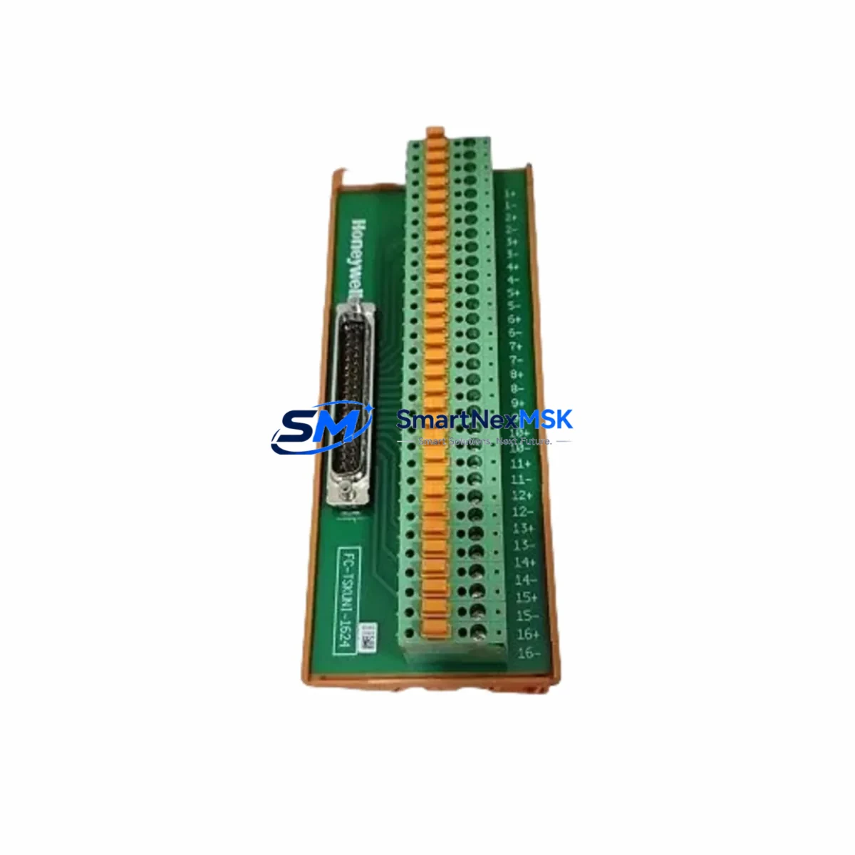
Honeywell FS-PDB-CPX05 Retrofit-Ready Power Distribution Board for CPX05 Control Systems
The Honeywell FS-PDB-CPX05 is a retrofit-ready power distribution board engineered for seamless integration into CPX05 panel series control systems. Whether you are replacing an end-of-life unit, upgrading an aging distributed control system (DCS), or restoring a critical production line after an unplanned failure, the FS-PDB-CPX05 delivers the electrical compatibility, mechanical fit, and firmware-level transparency that industrial engineers demand. Sourced directly from verified supply channels and backed by a 12-month warranty, every unit undergoes pre-shipment functional testing before dispatch.
This board serves as a direct replacement for legacy CPX05 power distribution assemblies found in process control cabinets across refining, chemical, power generation, and discrete manufacturing environments. Its terminal layout, backplane connector pitch, and voltage rail configuration match the original CPX05 specification, eliminating the need for custom wiring harnesses or panel re-engineering during a retrofit campaign.
Upgrade Compatibility Table
| Parameter | FS-PDB-CPX05 (This Unit) | Legacy CPX05 PDB | Retrofit Notes |
|---|---|---|---|
| Backplane Interface | CPX05 standard 64-pin DIN connector | CPX05 standard 64-pin DIN connector | Direct plug-in; no adapter required |
| Input Voltage Range | 24 VDC ± 10% | 24 VDC ± 10% | Verify upstream PSU capacity before swap |
| Output Rails | 5 VDC, 24 VDC distributed | 5 VDC, 24 VDC distributed | Rail sequencing identical; no re-parameterization |
| Terminal Wiring | Screw-clamp, 2.5 mm² max | Screw-clamp, 2.5 mm² max | Existing field cables reusable |
| Module Address | Slot-based, auto-detected by CPX05 CPU | Slot-based, auto-detected | No address re-configuration required |
| Communication Compatibility | Profibus DP / Modbus RTU (via CPX05 CPU) | Profibus DP / Modbus RTU | Protocol stack unchanged; HMI tags remain valid |
| Rack / Chassis Fit | CPX05 standard rack, DIN rail mount | CPX05 standard rack | Mechanical dimensions identical |
| Program Compatibility | Fully transparent to CPX05 CPU logic | Fully transparent | No PLC program modification needed |
| Pre-Shipment Testing | 100% functional burn-in test | Varies by source | Test report available on request |
| Warranty | 12 Months | N/A (legacy / EOL) | Covers DOA, functional failure, and early-life defects |
Retrofit Planning for Existing Automation Systems
A successful CPX05 power distribution board replacement begins well before the maintenance window opens. Engineers should start by auditing the existing control cabinet layout: confirm the rack model, verify available slot positions, and document the current wiring schedule for all field terminals connected to the legacy PDB. In most CPX05 installations, the power distribution board sits adjacent to the Honeywell CPX05 CPU module and feeds downstream I/O assemblies including Honeywell FS-SDO-0824 digital output modules and FS-SDI-0824 digital input modules. These I/O modules draw regulated 24 VDC from the distribution board, so confirming that the replacement unit’s output current capacity meets the aggregate I/O load is a mandatory pre-retrofit step.
Power budget verification is critical. Sum the current draw of every module installed in the CPX05 rack — including any Honeywell FS-SAI-1620 analog input modules, FS-SAO-0820 analog output modules, and communication interface cards such as the Honeywell FS-PCI-PBUS Profibus interface module — and confirm the upstream 24 VDC power supply unit (PSU) can sustain the total load with at least a 20% headroom margin. If the existing PSU is undersized or approaching end-of-life, this retrofit is an ideal opportunity to replace it concurrently with a modern Honeywell PS-24VDC-10A panel power supply or equivalent rated unit.
Backplane seating and rack integrity must be inspected before installing the FS-PDB-CPX05. Check the CPX05 rack chassis for bent guide rails, corroded backplane pins, or cracked housing — issues that are common in panels that have operated for 10 or more years. If the rack itself shows signs of degradation, replacing it with a new Honeywell CPX05 rack chassis assembly at the same time eliminates a latent failure point. Once the new PDB is seated and the backplane connector is fully engaged, re-terminate all field wiring according to the original wiring schedule, torque screw-clamp terminals to specification, and verify continuity before energizing.
For systems that use Honeywell FTE (Fault Tolerant Ethernet) communication links or legacy Modbus RTU serial links between the CPX05 controller and upstream SCADA or DCS servers, confirm that the communication module — typically a Honeywell FS-PCI-MBUS Modbus interface card — is reseated correctly after the PDB swap. Communication link parameters, node addresses, and baud rate settings are stored in the CPU module’s non-volatile memory and are unaffected by a power distribution board replacement, but a link-level diagnostic scan after power-up is recommended to confirm end-to-end connectivity before returning the system to automatic control.
HMI screen validation is the final pre-handover step. Operators should confirm that all CPX05-sourced process values — analog inputs, digital status bits, and alarm states — are displaying correctly on the Honeywell Station or third-party SCADA HMI before signing off on the retrofit. Any tag discrepancies at this stage are almost always traceable to a loose I/O module connection rather than a PDB issue, and can be resolved by reseating the affected module without further program changes.
Downtime Control During System Migration
Minimizing unplanned downtime is the primary concern for any CPX05 power distribution board replacement. The recommended approach is a planned maintenance window of no more than 2–4 hours, executed during a scheduled production break or shift changeover. Before de-energizing the panel, export a full backup of the CPX05 CPU program using the engineering workstation and the appropriate Honeywell Control Builder or FDT/DTM programming cable. Store the backup on a local drive and a network share simultaneously. This ensures that even in the unlikely event of a CPU memory fault during power cycling, the control logic can be restored within minutes rather than hours.
During the swap, keep the field wiring labeled and photographed before disconnection. Use numbered terminal markers if the existing installation lacks them. The FS-PDB-CPX05’s screw-clamp terminals accept the same wire gauges as the legacy board, so no re-ferrulation is required. After installation, power up the rack in stages if the PSU supports soft-start sequencing: energize the PDB first, confirm the 5 VDC and 24 VDC rails are within tolerance using a calibrated multimeter, then allow the CPU module to boot. The CPX05 CPU performs a self-diagnostic on startup and will flag any module communication errors on its front-panel LED indicators before entering run mode.
Once the CPU enters run mode and all I/O modules report healthy status, transfer control from manual backup (if applicable) back to automatic, and monitor the first 30 minutes of operation closely. Log all analog values and compare them against pre-maintenance baseline readings to confirm measurement accuracy. Document the completed retrofit in the plant maintenance management system (CMMS) with the new module serial number, installation date, and 12-month warranty expiry date for future reference.
Retrofit Support FAQ
Q1: Is the FS-PDB-CPX05 a direct drop-in replacement for the original CPX05 power distribution board?
Yes. The FS-PDB-CPX05 matches the original CPX05 PDB in backplane connector type, terminal layout, output voltage rails, and mechanical dimensions. No wiring modifications, adapter plates, or program changes are required. Existing field cables can be re-terminated directly onto the replacement board using the original wiring schedule.
Q2: What pre-shipment testing does each unit undergo?
Every FS-PDB-CPX05 unit is subjected to a 100% functional burn-in test prior to dispatch. Testing covers input voltage tolerance, output rail regulation under load, backplane connector integrity, and thermal performance. A test report is available upon request. All units are covered by a 12-month warranty against manufacturing defects and early-life functional failures from the date of delivery.
Q3: Do I need to modify the CPX05 CPU program or HMI configuration after replacing the power distribution board?
No program or HMI modifications are required. The FS-PDB-CPX05 is fully transparent to the CPX05 CPU’s I/O scan and communication stack. Module addresses, Profibus node IDs, Modbus register maps, and HMI tag bindings remain unchanged. After installation and power-up, the CPU will automatically detect the new board and resume normal operation without any re-parameterization.
Q4: What should I verify regarding wiring compatibility and terminal connections before installation?
Confirm that all field cables are within the 0.5–2.5 mm² wire gauge range supported by the screw-clamp terminals. Verify that terminal torque values match the specification in the CPX05 installation manual (typically 0.5–0.6 Nm for signal terminals). Inspect cable insulation for heat damage or brittleness — a common finding in panels that have operated for over a decade — and replace any degraded cables before re-termination. After wiring, perform a point-to-point continuity check against the original wiring schedule before energizing the board.
© 2026 SMARTNEXMSK. All rights reserved.
Original Source: https://smartnexmsk.com
Contact: [email protected] | +86 18259474341



