
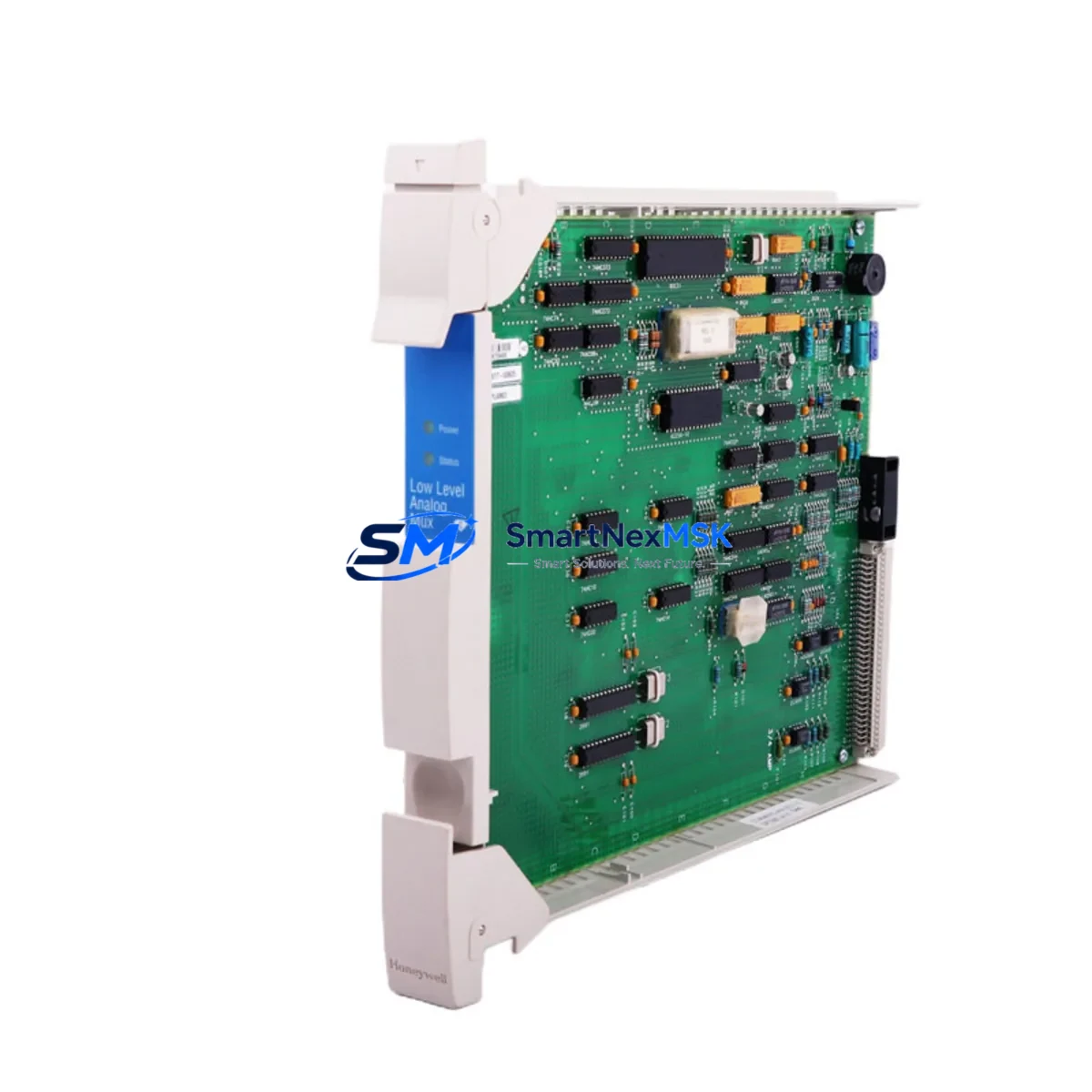
Honeywell MC-PLAM02 51304362-150 Maintenance-Ready Spare TDC 3000
The Honeywell MC-PLAM02 (P/N 51304362-150) is an original analog multiplexer module designed for the TDC 3000 and TPS distributed control systems. For maintenance engineers managing aging DCS infrastructure, this module represents a critical spare that directly impacts process uptime. Whether you are executing a planned turnaround, responding to an unscheduled fault, or building a strategic spare parts inventory for a long-running refinery or chemical plant, the MC-PLAM02 is a high-priority line item on any TDC 3000 maintenance BOM.
Sourced from verified original stock, each unit undergoes pre-shipment functional inspection to confirm signal integrity, channel isolation, and connector condition before dispatch. With a 12-month warranty covering manufacturing defects and operational failure under normal service conditions, procurement engineers can confidently include this module in both emergency and scheduled replenishment orders.
Spare Maintenance Table
| Parameter | Specification |
|---|---|
| Part Number | MC-PLAM02 / 51304362-150 |
| Manufacturer | Honeywell Process Solutions |
| Module Type | Analog Multiplexer Module |
| Compatible Systems | TDC 3000, TPS (Total Plant Solution) |
| Signal Type | Analog Input (AI) multiplexed channels |
| Operating Voltage | Per TDC 3000 backplane specification (typically 24 VDC bus) |
| Installation | Card cage / backplane slot insertion, standard TDC 3000 form factor |
| Operating Temperature | 0°C to 60°C (standard industrial control room environment) |
| Condition | Original, tested, pre-shipment inspected |
| Warranty | 12 Months — covers manufacturing defects and operational failure |
| Shipping | ESD-safe packaging, worldwide express available |
| Lead Time | In-stock: ships within 1–3 business days |
Maintenance Planning for Continuous Operation
When a TDC 3000 system experiences an analog input fault traced to the MC-PLAM02, the failure rarely occurs in isolation. A thorough maintenance response requires inspecting the broader signal chain and power distribution architecture within the same control cabinet. Maintenance engineers should simultaneously verify the condition of the associated MC-TAIX12 analog input termination assembly and the MC-PAIH02 analog input highway interface module, as these components share the same signal path and are subject to comparable wear cycles in high-cycle process environments.
Power integrity is equally critical. The MC-PSIM11 power supply input module and associated MC-PDIY22 digital I/O power distribution module should be checked for voltage stability and ripple, particularly in installations where the control room UPS has not been serviced recently. A degraded power supply is a common root cause of intermittent analog channel faults that are initially misdiagnosed as module failures.
For sites running hybrid TDC 3000 / TPS architectures, the MC-PLAM02 often operates alongside MC-TDIY22 digital I/O modules and MC-COMM03 communication interface cards. During any corrective maintenance event involving the analog multiplexer, it is good practice to inspect these adjacent modules for connector oxidation, backplane pin wear, and firmware revision alignment — especially if the system has not undergone a full cabinet inspection within the past 18 months.
Relay output modules such as the MC-DOLA22 digital output relay module located in the same cabinet should also be included in the inspection checklist. Relay contact wear and coil degradation can introduce ground loops that manifest as analog signal drift — a symptom that is frequently attributed to the multiplexer module before the true source is identified.
For sites with signal conditioning requirements, verifying the calibration status of any signal isolators or loop-powered transmitters connected to the MC-PLAM02 input channels is essential before declaring the replacement successful. A post-replacement loop check across all active channels, confirmed against the DCS historian trend, is the recommended acceptance criterion before returning the loop to automatic control.
Site Replacement Workflow
Step 1 — Isolation and Documentation: Place the affected loop in manual mode at the operator station. Document the current process variable reading, alarm state, and any active interlocks associated with the faulty module’s channels. Photograph the existing module label and wiring termination before removal.
Step 2 — Safe Removal: De-energize the card cage slot per site LOTO procedure. For TDC 3000 systems with hot-swap capability, confirm whether the specific backplane revision supports live extraction before proceeding. Remove the MC-PLAM02 by releasing the front-panel ejector levers and sliding the card straight out along the guide rails.
Step 3 — Replacement Verification: Confirm the replacement MC-PLAM02 (51304362-150) revision matches or is backward-compatible with the installed system firmware. Check the module’s hardware revision label against the system’s hardware compatibility matrix in the TDC 3000 engineering documentation.
Step 4 — Installation and Loop Check: Insert the replacement module, re-energize the slot, and allow the DCS to complete its self-diagnostic cycle. Perform a full channel loop check, verifying 4–20 mA signal fidelity across all active input channels. Compare live readings against the historian baseline to confirm signal accuracy within specification.
Step 5 — Return to Service: Transfer affected loops from manual to automatic control sequentially, monitoring for alarm recurrence. Update the maintenance management system (CMMS) with the replacement record, including the removed module’s serial number, failure mode, and replacement date.
This workflow is applicable to both emergency corrective replacements and planned preventive swap-outs during scheduled turnarounds. Maintaining a minimum of one MC-PLAM02 unit in the site spare parts store is recommended for any facility operating more than four TDC 3000 cabinets.
Spare Parts Support FAQ
Q1: Is the MC-PLAM02 51304362-150 compatible with both TDC 3000 and TPS systems?
Yes. The MC-PLAM02 with part number 51304362-150 is designed for use across the Honeywell TDC 3000 and TPS (Total Plant Solution) platform families. Compatibility is determined by backplane revision and system firmware version. We recommend confirming your system’s hardware compatibility matrix before installation. Our technical team can assist with compatibility verification prior to order confirmation.
Q2: What pre-shipment testing is performed on each unit?
Each MC-PLAM02 unit undergoes a functional inspection covering connector integrity, channel isolation verification, and visual inspection for physical damage or component degradation. Units are shipped in ESD-safe anti-static packaging with desiccant to prevent moisture ingress during transit. A test report is available upon request for quality-critical procurement processes.
Q3: What does the 12-month warranty cover?
The 12-month warranty covers manufacturing defects and operational failure under normal industrial service conditions. It does not cover damage resulting from incorrect installation, overvoltage events, physical impact, or use outside the module’s rated environmental specifications. Warranty claims are processed with a replacement-first policy to minimize site downtime.
Q4: Can you support long-term or blanket purchase orders for TDC 3000 spare parts?
Yes. For facilities managing multi-year maintenance contracts or executing phased system life-extension programs, we support blanket purchase orders, consignment stock arrangements, and scheduled delivery programs. Contact our sales team to discuss volume pricing, lead time commitments, and multi-SKU spare parts kitting for TDC 3000 and TPS platforms.
© 2026 SMARTNEXMSK. All rights reserved.
Original Source: https://smartnexmsk.com
Contact: [email protected] | +86 18259474341



