
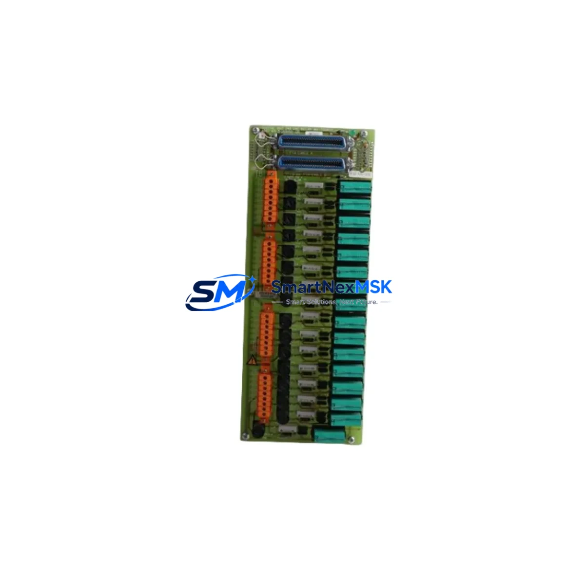
Honeywell MC-TSTX13 51309142-175 Maintenance-Ready Spare TPS DCS
The Honeywell MC-TSTX13 (Part No. 51309142-175) is an original digital output relay module engineered for the TotalPlant Solution (TPS) Distributed Control System platform. In industrial facilities where continuous process uptime is non-negotiable — refineries, chemical plants, power generation, and pulp & paper operations — this module serves as a critical interface between the DCS controller and field-side actuators, solenoids, and motor starters. Sourced directly from verified supply channels, each unit is inspected, function-tested, and shipped with a 12-month warranty, giving maintenance engineers and procurement teams the confidence to stock it as a primary spare.
Unplanned downtime caused by a failed digital output relay module can cascade rapidly across a control loop. The MC-TSTX13 is designed for rapid field replacement: it slots into the standard TPS I/O carrier without rewiring, preserving existing termination integrity and minimizing the mean time to repair (MTTR). For facilities running legacy TPS cabinets alongside newer Experion PKS nodes, maintaining a verified stock of MC-TSTX13 units is a proven strategy to bridge the technology gap and extend system life without a full migration.
From a procurement standpoint, the 51309142-175 revision designation is essential for compatibility verification. Maintenance planners should confirm the revision level against the installed base before ordering, particularly in mixed-revision TPS racks where module firmware and backplane signaling must align. Our team provides pre-shipment revision confirmation and functional burn-in testing as standard practice.
Spare Maintenance Table
| Parameter | Specification |
|---|---|
| Part Number | MC-TSTX13 |
| Honeywell P/N | 51309142-175 |
| Module Type | Digital Output Relay Module |
| Platform Compatibility | Honeywell TPS (TotalPlant Solution) DCS |
| Output Type | Relay contact (dry contact) digital output |
| Channels | 8-channel DO (typical TPS relay output configuration) |
| Operating Voltage | 24 VDC nominal (field side); 5 VDC backplane logic |
| Contact Rating | Up to 2A resistive per channel (verify against site SIL requirements) |
| Backplane Interface | TPS standard I/O carrier slot — hot-swap capable |
| Country of Origin | Germany (DE) |
| Weight | 700 g |
| Operating Temperature | 0°C to 60°C (32°F to 140°F) |
| Humidity | 5% to 95% RH, non-condensing |
| Installation Environment | Control room / marshalling cabinet; IEC 61010 compliant enclosure |
| Maintenance Recommendation | Inspect relay contacts and backplane connector annually; replace at first sign of contact degradation or intermittent output faults |
| Warranty | 12 months from date of shipment |
| Pre-shipment Testing | Functional burn-in and output channel verification included |
Maintenance Planning for Continuous Operation
When a maintenance engineer identifies a fault on the MC-TSTX13 during a control cabinet inspection or DCS alarm review, the replacement workflow rarely ends with the module alone. A thorough site assessment should extend to the surrounding I/O infrastructure to prevent repeat failures and ensure the restored loop performs reliably.
Start with the MC-TAIX11 analog input module and MC-TAOX11 analog output module installed in adjacent slots of the same TPS I/O carrier — shared backplane power transients from a failing relay module can stress neighboring I/O cards. Inspect the MC-PAIH03 power supply module that feeds the I/O carrier; a degraded power rail is a common root cause of intermittent relay output faults that are misdiagnosed as module failures.
Check the MC-TDIY22 digital input module on the same carrier for contact bounce or signal integrity issues — in interlock loops, a faulty digital input paired with a degraded digital output relay creates dangerous ambiguity in the control logic. The MC-TLPA02 termination panel and its associated field wiring terminals should be inspected for corrosion, loose terminations, and insulation degradation, particularly in high-humidity or chemically aggressive environments.
For facilities using Honeywell HPM (High-Performance Process Manager) nodes connected to TPS I/O subsystems, verify that the HPM’s I/O link communication is stable after module replacement — a brief link interruption during hot-swap can trigger nuisance alarms in the Honeywell GUS (Global User Station) or connected HMI consoles. If the site uses signal isolators between the DCS output and field devices, inspect the isolator barrier for drift or failure, as relay contact arcing can degrade isolator input stages over time.
Finally, review the fuse and circuit protection on the field-side wiring connected to the relay outputs. A blown fuse or tripped miniature circuit breaker (MCB) on the load side is frequently the initiating event that caused the relay module to fail in the first place. Replacing the MC-TSTX13 without restoring proper field-side protection will result in repeat failure within weeks.
Site Replacement Workflow
Step 1 — Isolation and permit: Obtain a Permit to Work (PTW) and isolate the affected output loop at the marshalling cabinet. Confirm the field device (solenoid, motor starter, or valve actuator) is in a safe state before proceeding.
Step 2 — Revision verification: Confirm the replacement MC-TSTX13 51309142-175 revision matches the installed module. Check the label on the module faceplate and cross-reference with the TPS hardware configuration database.
Step 3 — Hot-swap removal: The TPS I/O carrier supports hot-swap on most configurations. Slide the module out of the carrier slot without powering down the carrier, unless site safety procedures require a full de-energization. Note the slot address for DCS configuration verification.
Step 4 — Installation and seating: Insert the replacement MC-TSTX13 firmly into the carrier slot until the locking tab engages. Verify the module status LED sequence on power-up — a solid green indicates successful backplane communication and self-test pass.
Step 5 — DCS configuration check: From the Honeywell GUS or Engineering Workstation, confirm the I/O point assignments for the replaced slot are intact. Force-test each output channel from the DCS to verify field device response before releasing the loop to automatic control.
Step 6 — Documentation: Update the maintenance management system (CMMS) with the replacement date, module serial number, and post-replacement test results. Log the failed module for root cause analysis and warranty claim processing if applicable.
This workflow is applicable to both planned maintenance windows and emergency breakdown replacements. For emergency scenarios, having a pre-tested MC-TSTX13 unit on the shelf — with revision confirmed and burn-in completed — reduces the replacement cycle to under 30 minutes in most TPS cabinet configurations.
Spare Parts Support FAQ
Q1: How do I confirm the MC-TSTX13 51309142-175 is compatible with my TPS DCS version?
The 51309142-175 part number includes the revision suffix that determines backplane and firmware compatibility. Provide your TPS system version and I/O carrier model number to our technical team before ordering. We cross-reference against Honeywell’s hardware compatibility matrix and confirm in writing prior to shipment. For mixed-revision racks, we can supply matched pairs or sets to maintain consistency across the carrier.
Q2: What does pre-shipment testing include, and how does it support my warranty claim process?
Every MC-TSTX13 unit is subjected to a functional burn-in test that exercises all 8 output relay channels under load, verifies backplane communication signaling, and checks contact resistance against factory specification. A test report is included with each shipment. This documentation serves as the baseline for any warranty claim within the 12-month coverage period — if a unit fails in service, the test report establishes the pre-shipment condition and supports a straightforward replacement or refund process.
Q3: What is the recommended spare parts inventory strategy for TPS digital output relay modules?
For a TPS system with 10 or more MC-TSTX13 slots in service, industry best practice recommends maintaining a minimum of 2 units as on-shelf critical spares, with a reorder trigger at 1 unit remaining. For facilities with extended lead times or remote locations, a 3-unit buffer is advisable. Given that Honeywell TPS is a mature platform with a finite production lifecycle, early procurement of verified original spares is strongly recommended to avoid counterfeit risk and supply gaps as the platform ages.
Q4: Can the MC-TSTX13 be used as a direct replacement for older TPS relay output modules with different part numbers?
In many cases, yes — Honeywell issued successive part number revisions for the TPS digital output relay module family as component updates were made, and later revisions are typically backward-compatible with earlier carrier hardware. However, compatibility must be verified on a case-by-case basis. Contact our technical team with the original part number and TPS carrier model, and we will confirm interchangeability before shipment. We do not recommend field-substituting modules without written compatibility confirmation.
© 2026 SMARTNEXMSK. All rights reserved.
Original Source: https://smartnexmsk.com
Contact: [email protected] | +86 18259474341



