
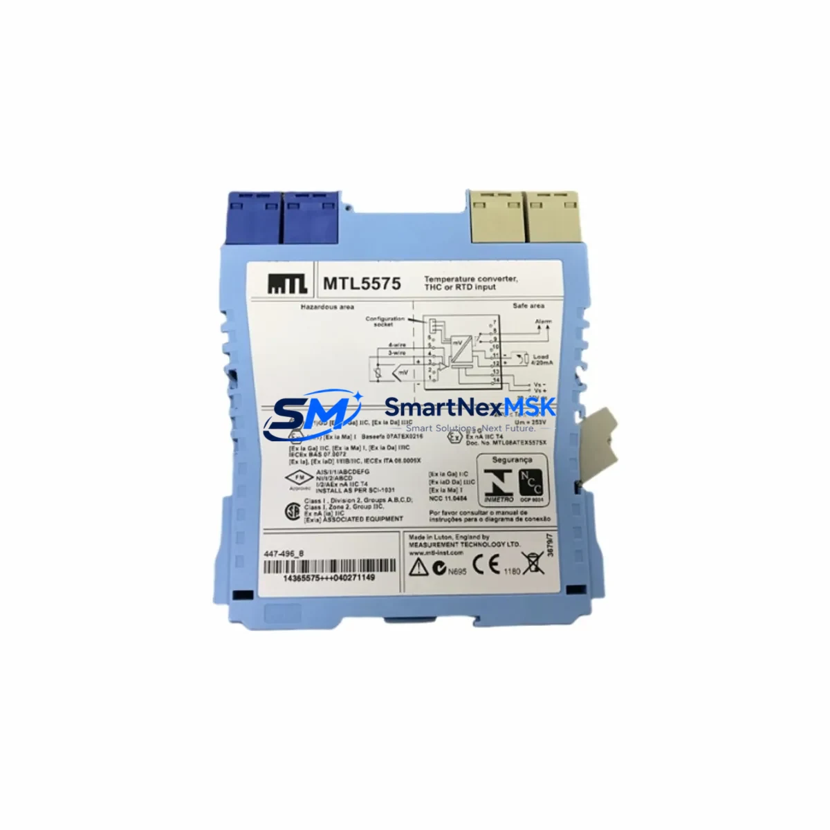
Honeywell MTL5575 Retrofit-Ready Signal Isolator for MTL5000 Control Systems
The Honeywell MTL5575 is a high-performance temperature converter and 4-20mA signal isolator engineered for seamless integration into existing MTL5000 Series control architectures. Designed with retrofit compatibility as a core requirement, the MTL5575 addresses the growing demand for reliable, drop-in replacements in aging DCS and PLC-based process control environments where legacy MTL5000 modules have reached end-of-life or are no longer available through standard supply channels.
Industrial facilities operating Honeywell TDC 3000, Experion PKS, or third-party DCS platforms frequently encounter the challenge of sourcing discontinued MTL5000 Series isolators. The MTL5575 provides a verified upgrade path that preserves existing field wiring, terminal block assignments, and DIN rail mounting configurations — dramatically reducing the engineering effort and downtime associated with a full I/O card replacement. Engineers responsible for control cabinet upgrades can retain the existing MTL5000 backplane layout while substituting individual modules without modifying the marshalling panel or re-terminating field cables.
Before committing to a retrofit using the MTL5575, site engineers should verify several critical parameters. Power supply capacity must be confirmed against the module’s 24 VDC loop supply requirements, particularly in multi-drop installations where the MTL5041 or MTL5049 power supply modules are shared across multiple isolator channels. Terminal wiring compatibility should be cross-checked against the original MTL5575 datasheet, as field-side and safe-side terminal assignments must align with the existing marshalling schedule. Backplane interface dimensions and DIN rail clip spacing should be measured against the installed MTL5000 carrier to confirm mechanical fit without modification.
Module addressing and channel configuration are equally important during the commissioning phase. If the host DCS or PLC — such as a Honeywell C300 controller or a Siemens S7-400 with PROFIBUS DP — references specific I/O channel addresses mapped to the original MTL5000 module, the replacement MTL5575 must be configured to match those address assignments. In installations where the MTL5041 or MTL5049 acts as the segment power conditioner, the new module’s loop resistance and current draw must remain within the segment’s power budget to avoid nuisance trips or signal degradation.
Program compatibility is a frequent concern during MTL5000 to MTL5575 transitions. Control logic residing in the DCS historian or in ladder programs on a Rockwell ControlLogix or Allen-Bradley PLC-5 platform typically references engineering unit scaling, alarm limits, and HART pass-through parameters tied to the original module’s signal range. These parameters should be reviewed and validated in the DCS configuration tool — such as Honeywell Control Builder or Siemens STEP 7 — before the replacement module is energized in the field. HMI faceplates and trend displays referencing the affected loop should also be verified to ensure that tag names, display ranges, and alarm annunciation remain consistent after the swap.
Communication link integrity is another key checkpoint. In installations where HART communication is used for remote valve positioner diagnostics or transmitter configuration, the MTL5575’s HART transparency must be confirmed against the host asset management system — such as Honeywell Field Device Manager or Emerson AMS Device Manager. If the existing MTL5000 module was configured as a HART multiplexer gateway, the replacement module’s HART pass-through behavior should be validated with a HART communicator prior to returning the loop to service.
On-site commissioning of the MTL5575 typically follows a structured sequence: isolate the loop, remove the legacy module, install the replacement on the existing DIN rail carrier, re-terminate field and safe-side wiring per the updated marshalling schedule, restore power, and verify the 4-20mA output signal at the DCS input card. A calibration check using a Fluke 725 or equivalent process calibrator confirms that the signal chain — from the field transmitter through the MTL5575 to the DCS analog input — is within the specified ±0.1% accuracy tolerance. Loop current and voltage readings at the MTL5041 power supply terminals should be logged as part of the commissioning record.
For facilities managing a broader MTL5000 Series phase-out, the MTL5575 is commonly deployed alongside the MTL5544, MTL5546, MTL5553, and MTL5581 isolators, which cover discrete input, discrete output, and analog output functions within the same MTL5000 carrier system. Control cabinet upgrades that include the MTL5575 often also involve replacing the MTL5000 Series Zener barriers with modern galvanic isolators, updating the MTL5041 segment power supply to a higher-capacity unit, and migrating HART device configurations to a centralized asset management platform. In multi-rack installations, the MTL5000 backplane and rack assembly itself may be retained, with only the individual module slots updated to current-generation equivalents.
SMARTNEXMSK maintains verified stock of the MTL5575 and supports urgent retrofit requirements with expedited shipping and pre-shipment functional testing. Each unit is supplied with a 12-month warranty covering manufacturing defects and signal performance within published specifications. Our technical team can assist with cross-referencing legacy MTL5000 part numbers, confirming terminal wiring compatibility, and providing documentation support for site acceptance testing.
Upgrade Compatibility Table
| Parameter | Legacy MTL5000 Module | MTL5575 Replacement | Action Required |
|---|---|---|---|
| Mounting | DIN rail, MTL5000 carrier | DIN rail, MTL5000 carrier | None — direct fit |
| Terminal Wiring | Screw terminals, existing schedule | Identical terminal layout | Verify marshalling schedule |
| Signal Range | 4-20mA / Thermocouple input | 4-20mA / TC / RTD input | Confirm input type selection |
| Power Supply | 24 VDC via MTL5041/MTL5049 | 24 VDC via MTL5041/MTL5049 | Verify segment power budget |
| HART Communication | HART pass-through (model dependent) | HART transparent | Validate with HART communicator |
| DCS Compatibility | Honeywell TDC 3000 / Experion PKS | Universal analog input | Verify I/O channel address mapping |
| Installation Standard | IEC 60079 / ATEX Zone 1 | IEC 60079 / ATEX Zone 1 | Confirm hazardous area certification |
| Commissioning | Loop calibration required | Loop calibration required | Use process calibrator on-site |
| Warranty | N/A (discontinued) | 12 months from shipment | Covered by SMARTNEXMSK warranty |
Retrofit Planning for Existing Automation Systems
A successful MTL5575 retrofit begins with a comprehensive audit of the existing control cabinet. Identify all MTL5000 Series modules currently installed — including the MTL5544 discrete input isolators, MTL5546 discrete output isolators, MTL5553 analog output isolators, and MTL5581 frequency input isolators — and map each module to its corresponding DCS or PLC I/O channel. This audit forms the basis of the replacement schedule and allows the engineering team to sequence module swaps to minimize process disruption.
The MTL5041 and MTL5049 segment power supply modules are critical infrastructure components that must be evaluated before any module replacement begins. Confirm that the existing power supply can support the combined current draw of all modules in the segment after the MTL5575 is installed. If the power budget is marginal, consider upgrading to a higher-capacity MTL5041 unit as part of the same maintenance window. Similarly, the MTL5000 backplane and rack assembly should be inspected for corrosion, loose connectors, or mechanical damage that could affect module seating and signal integrity.
For installations that include Honeywell UDC 3500 or UDC 2800 loop controllers communicating via RS-485 Modbus, the MTL5575’s signal output must be verified against the controller’s analog input scaling. If the facility also operates Yokogawa CENTUM VP or ABB 800xA DCS platforms in adjacent process areas, ensure that the HART device database is updated to reflect the new module’s device descriptor before the replacement is commissioned. Programming cables such as the MTL USB-HART modem or equivalent HART interface should be available on-site during commissioning to support live device configuration and loop testing.
Downtime Control During System Migration
Minimizing unplanned downtime during an MTL5575 retrofit requires careful pre-staging and a disciplined change management process. Before the maintenance window opens, pre-configure the replacement MTL5575 module on the bench — set the input type selection switches, verify the output signal range, and perform a bench calibration using a traceable process calibrator. Document the configuration settings and retain them as part of the site acceptance test record.
During the swap, isolate only the affected loop rather than shutting down the entire I/O segment. Most MTL5000 carrier systems allow individual module removal without de-energizing adjacent channels, which preserves control continuity for other loops sharing the same backplane. After installing the MTL5575, restore the loop in manual mode at the DCS workstation before switching to automatic control — this allows the operator to verify the process variable reading before committing the loop to closed-loop control. Log the pre- and post-replacement loop current readings, and retain the original MTL5000 module as a spare until the replacement has been validated through at least one full process cycle.
For critical loops where even brief interruption is unacceptable, consider a parallel wiring strategy: install the MTL5575 on a spare DIN rail position, wire it in parallel with the existing module, verify the output signal, and then transfer the field wiring in a single cut-over step. This approach reduces the live wiring time to under five minutes and eliminates the risk of signal loss during the transition.
Retrofit Support FAQ
Q: Is the MTL5575 a direct drop-in replacement for all MTL5000 Series temperature converter modules?
A: The MTL5575 is a direct mechanical and electrical replacement for MTL5000 Series temperature converter and 4-20mA isolator modules with equivalent input/output specifications. Terminal wiring and DIN rail mounting are compatible. Input type selection (TC, RTD, or mA) must be confirmed against the original module’s configuration before installation.
Q: What commissioning steps are required after installing the MTL5575?
A: After installation, perform a loop calibration using a traceable process calibrator to verify the 4-20mA output signal at the DCS analog input card. Confirm HART communication transparency if the loop uses HART-enabled field devices. Verify DCS tag scaling, alarm limits, and HMI display ranges before returning the loop to automatic control.
Q: Can the MTL5575 be used in ATEX Zone 1 hazardous area installations?
A: Yes. The MTL5575 carries IEC 60079 and ATEX certification for use in Zone 1 hazardous areas when installed in accordance with the applicable installation standard and the module’s entity parameters. Confirm that the field device’s entity parameters are compatible with the MTL5575’s safe-area output specifications before installation.
Q: What warranty coverage does SMARTNEXMSK provide for the MTL5575?
A: Every MTL5575 unit supplied by SMARTNEXMSK is covered by a 12-month warranty from the date of shipment. The warranty covers manufacturing defects and signal performance within published specifications. Pre-shipment functional testing is performed on all units. Contact [email protected] for warranty claims or technical support.
© 2026 SMARTNEXMSK. All rights reserved.
Original Source: https://smartnexmsk.com
Contact: [email protected] | +86 18259474341



