
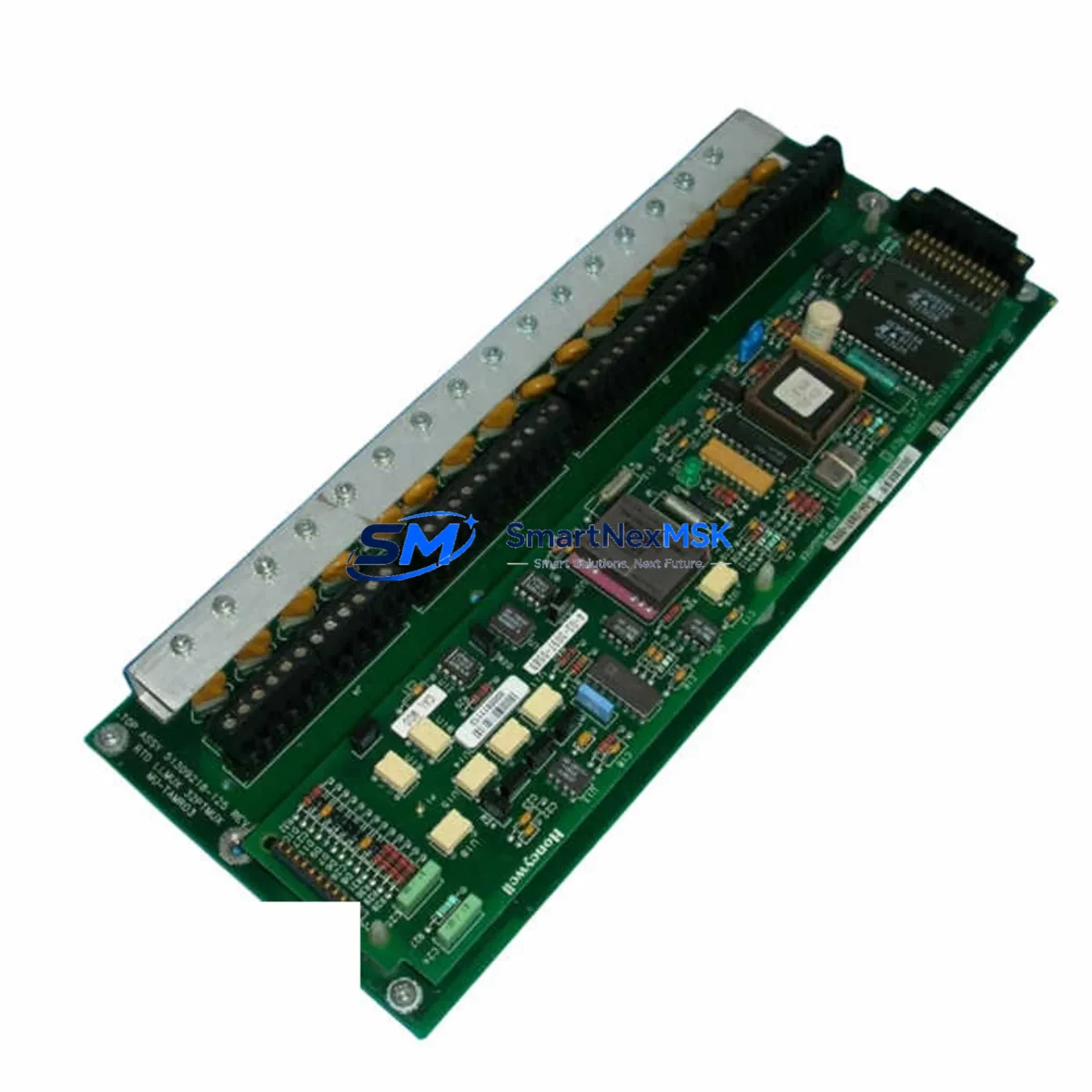
Honeywell MU-TAMR03 51309218-125 Maintenance-Ready Spare for TPS Automation
The Honeywell MU-TAMR03 (part number 51309218-125) is an original low-level analog multiplexer module designed for the TotalPlant Solution (TPS) Distributed Control System platform. In industrial facilities running continuous processes — refining, petrochemical, power generation, and advanced manufacturing — this module serves as a critical signal conditioning and multiplexing component within the process control cabinet. When this module fails or degrades, the result is immediate: loss of analog input visibility, compromised loop control, and unplanned downtime that can cost thousands of dollars per hour. Maintaining a verified, tested spare on the shelf is the single most effective strategy for rapid fault recovery and sustained system availability.
At SMARTNEXMSK, every MU-TAMR03 51309218-125 unit is sourced as an original Honeywell component, subjected to pre-shipment functional testing, and backed by a 12-month warranty. Our inventory is maintained specifically to support maintenance engineers and procurement teams who cannot afford lead-time uncertainty when a critical DCS module fails in the field.
Spare Maintenance Table
| Parameter | Specification / Detail |
|---|---|
| Part Number | MU-TAMR03 / 51309218-125 |
| Brand | Honeywell |
| Series / Platform | TPS (TotalPlant Solution) DCS |
| Module Type | Low-Level Analog Multiplexer Module |
| Signal Type | Low-level analog inputs (thermocouple, mV, RTD compatible) |
| Channel Capacity | Multi-channel multiplexed analog input |
| Compatibility | Honeywell TPS DCS cabinets; replaces legacy MU-TAMR03 variants |
| Installation | Card-slot insertion into TPS I/O carrier / backplane |
| Operating Environment | Industrial control room; 0–60°C, humidity-controlled enclosure |
| Country of Origin | Germany |
| Condition | Original, pre-tested, ready to ship |
| Maintenance Recommendation | Inspect signal wiring, terminal blocks, and carrier backplane on replacement |
| Warranty | 12 Months — covers functional defects under normal operating conditions |
Maintenance Planning for Continuous Operation
When a maintenance or reliability engineer schedules replacement of the MU-TAMR03 51309218-125, the scope of inspection should extend well beyond the module itself. The TPS DCS architecture distributes signal acquisition, power conditioning, and communication across multiple interdependent components within the same control cabinet. A disciplined replacement workflow should include verification of the following associated components:
Power Supply Module (e.g., MC-PDOY22 or equivalent TPS power carrier): Confirm that the DC bus voltage supplying the I/O carrier is within specification. A marginal power supply is a common root cause of intermittent analog module faults and should be inspected or replaced concurrently.
I/O Carrier / Backplane: Inspect the card-edge connector and backplane slot for oxidation, bent pins, or contamination. A degraded backplane connection will cause the replacement MU-TAMR03 to exhibit the same fault symptoms as the failed unit.
Field Terminal Assemblies (FTA) and Terminal Blocks: Verify that all field wiring terminations are secure, correctly labeled, and free of corrosion. Loose or corroded terminals on the FTA are a leading cause of signal drift and false readings on analog multiplexer channels.
Signal Cables and Shielded Wiring Harnesses: Check cable routing, shield grounding, and connector integrity between the FTA and the MU-TAMR03 carrier. Damaged shielding introduces noise that can mask the improvement gained from installing a new module.
Analog Input Modules in Adjacent Slots (e.g., MU-TAIH02, MU-TAIH12): If the fault affected multiple channels or loops, adjacent analog input modules should be tested. A single failing module can introduce ground loops or reference voltage errors that affect neighboring cards.
Communication Interface Modules (e.g., MC-COMM series): Confirm that the UCN or LCN communication path to the affected I/O subsystem is healthy. A communication module fault can be misdiagnosed as an analog input module failure.
Fuses and Circuit Protection: Replace any blown fuses in the I/O power distribution circuit. Document fuse ratings and verify that replacements match the original specification to avoid nuisance trips or under-protection.
Relay Output Modules and Interposing Relays: If the affected control loop drives relay outputs or interposing relays (e.g., MC-TAOY22), inspect coil continuity and contact condition. A failed relay can prevent loop closure even after the analog module is restored.
Signal Isolators and Barriers: For loops connected to hazardous area field instruments, verify that Zener barriers or galvanic isolators are within calibration and have not been damaged by the fault event.
HMI and Operator Station Connectivity: After module replacement, confirm that the TPS operator station (e.g., GUS or Universal Station) correctly reflects the restored analog values. A configuration mismatch or stale alarm state can indicate a deeper system issue requiring attention.
Site Replacement Workflow
Replacing the MU-TAMR03 51309218-125 in a live TPS DCS environment requires a structured approach to minimize downtime and avoid introducing new faults. The following workflow is recommended for maintenance engineers performing a hot-swap or planned replacement:
1. Pre-Replacement Verification: Confirm the replacement unit’s part number (MU-TAMR03, 51309218-125) matches the installed module exactly. Cross-reference the Honeywell TPS hardware manual to verify slot assignment and carrier compatibility. Do not substitute with a different revision unless compatibility has been confirmed with Honeywell documentation or engineering review.
2. Loop Isolation and Mode Transfer: Place all affected control loops in manual mode at the operator station before removing the module. Notify the control room operator and document the current process values for reference during restoration.
3. Module Removal: Follow ESD precautions. Remove the module from its carrier slot using the extraction handle. Inspect the card-edge connector on the removed module for burn marks, corrosion, or physical damage that may indicate a root cause beyond the module itself.
4. Carrier and Backplane Inspection: Before inserting the replacement module, inspect the carrier slot for debris, bent pins, and connector integrity. Clean with appropriate contact cleaner if required.
5. Module Insertion and System Recognition: Insert the replacement MU-TAMR03 firmly into the carrier slot. Observe the TPS system for module recognition and self-test completion. Confirm that the module status indicator shows a healthy state.
6. Loop Restoration and Verification: Return control loops to automatic mode one at a time. Verify that analog input values are within expected range and that no spurious alarms are generated. Document the replacement in the maintenance management system (CMMS).
7. Spare Parts Replenishment: Immediately initiate a purchase order to replenish the consumed spare. A zero-spare condition for a critical DCS module is an unacceptable risk posture for any continuous-process facility.
Spare Parts Support FAQ
Q1: What is the shelf life and storage recommendation for the MU-TAMR03 51309218-125 spare?
When stored in a dry, temperature-controlled environment (15–25°C, <60% RH) in its original anti-static packaging, the MU-TAMR03 can be held in spare inventory for 5–10 years without degradation of electronic components. Inspect annually for packaging integrity and re-test before deployment if stored for more than 3 years.
Q2: How is compatibility with my specific TPS DCS revision confirmed before shipment?
Our technical team cross-references the part number 51309218-125 against Honeywell TPS hardware compatibility matrices. If you provide your cabinet model, UCN node configuration, or existing module revision, we can confirm compatibility before the order is processed. All units are tested for basic functional operation prior to shipment.
Q3: What does the 12-month warranty cover, and what is the return process?
The 12-month warranty covers functional defects arising under normal operating conditions — including module failure to initialize, loss of channel output, and communication faults attributable to the module itself. Physical damage caused by incorrect installation, overvoltage, or environmental exposure is excluded. To initiate a warranty claim, contact our team with the order number and a fault description; we will arrange return shipping and replacement or repair within an agreed lead time.
Q4: Can SMARTNEXMSK support long-term supply for legacy TPS systems being extended beyond original end-of-life?
Yes. We specialize in supporting legacy Honeywell TPS and TDC 3000 systems that are being maintained beyond Honeywell’s standard product lifecycle. We maintain buffer stock of critical modules including analog multiplexers, power supplies, and communication cards to support planned maintenance cycles and emergency replacements. Contact our team to discuss a long-term supply agreement tailored to your facility’s maintenance schedule.
© 2026 SMARTNEXMSK. All rights reserved.
Original Source: https://smartnexmsk.com
Contact: [email protected] | +86 18259474341



