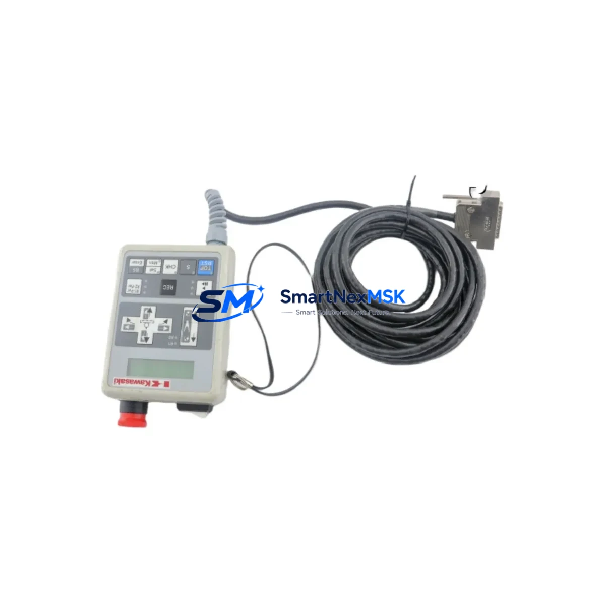
KAWASAKI 50978-3621L05 Spare for PX32J Automation: Spare Replacement & Industrial Downtime Risk Control
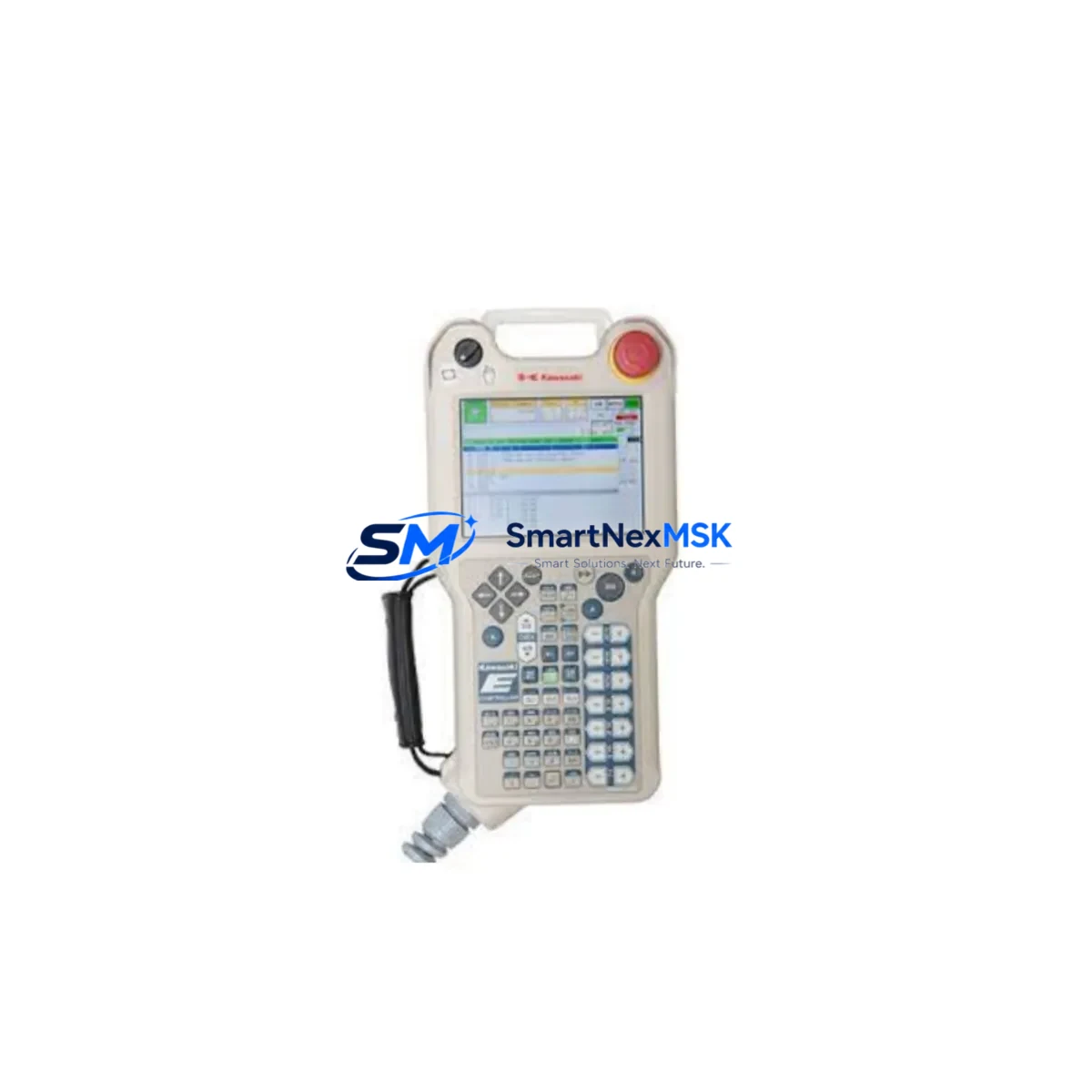
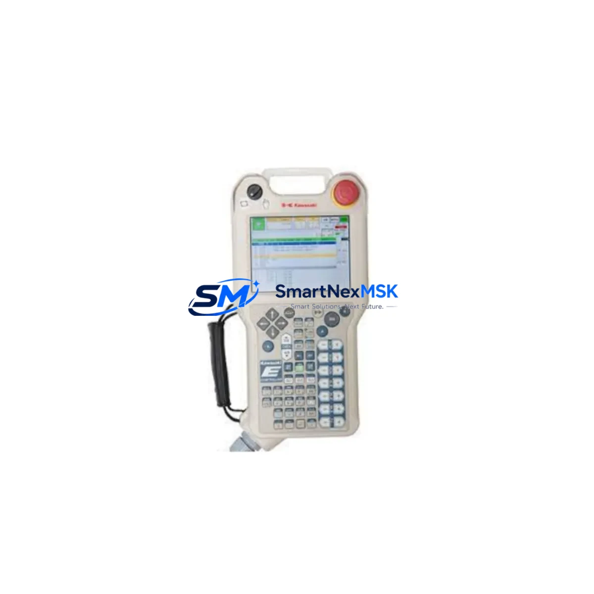
The KAWASAKI 50978-3621L05 (model PX32J, also cross-referenced as 9090-00639 and ESB-YSB4080AB500-01) is an original teach pendant designed for KAWASAKI PX-series industrial robot controllers. In maintenance-critical environments — automotive assembly, arc welding cells, material handling lines, and precision manufacturing — the teach pendant is the primary human-machine interface for robot programming, jog operation, fault acknowledgment, and safety override. A failed or damaged pendant brings the entire robot cell to a halt. Stocking a verified replacement unit of the 50978-3621L05 is a foundational element of any serious spare parts strategy for PX-series installations.
This unit is sourced as an original KAWASAKI component, pre-tested prior to shipment, and backed by a 12-month warranty. It is suitable for direct field replacement without controller reconfiguration in compatible PX-series systems.
Spare Maintenance Table
| Parameter | Specification / Detail |
|---|---|
| Part Number | 50978-3621L05 |
| Model | PX32J |
| Cross Reference | 9090-00639 / ESB-YSB4080AB500-01 |
| Brand | KAWASAKI |
| Series Compatibility | KAWASAKI PX-Series Robot Controllers |
| Component Type | Robot Teach Pendant (Operator Programming Terminal) |
| Origin | Japan |
| Weight | Approx. 2,600 g (with cable) |
| Interface | Dedicated KAWASAKI controller pendant port |
| Safety Features | Deadman switch, emergency stop button |
| Display | Integrated LCD / touch interface (PX32J configuration) |
| Application Environment | Industrial robot cells, welding lines, assembly automation |
| Installation | Plug-and-play replacement on compatible PX-series controllers |
| Condition | Original spare, pre-tested before shipment |
| Warranty | 12 Months |
| Lead Time | In-stock units ship within 3–5 business days |
Maintenance Planning for Continuous Operation
When a KAWASAKI 50978-3621L05 teach pendant fails or is scheduled for replacement during planned maintenance, a thorough inspection of the surrounding control architecture is essential to prevent repeat failures and ensure full system restoration. Maintenance engineers should treat pendant replacement as an opportunity to audit the entire robot control cabinet.
Begin with the pendant cable and connector assembly — the spiral cable between the pendant and controller is subject to repeated flexing and is a common wear point. Inspect for insulation cracking, connector pin corrosion, or intermittent continuity. Next, verify the controller power supply unit within the PX-series cabinet; an unstable DC rail can cause pendant communication errors that mimic pendant hardware failure. Check the emergency stop relay module and safety circuit continuity — the deadman switch circuit on the 50978-3621L05 feeds directly into the robot’s safety chain, and any degraded relay contact will prevent robot enable.
For systems using KAWASAKI PX-series I/O expansion boards, inspect the I/O terminal blocks and wiring harnesses for loose connections that may have been disturbed during pendant removal. If the robot cell includes a fieldbus communication module (DeviceNet, PROFIBUS, or EtherNet/IP), confirm that the network address and baud rate settings are preserved after controller restart. In cells with external operator panels or HMI touchscreens connected to the same controller, verify that the HMI communication link remains stable after pendant swap.
Older PX-series installations may also rely on signal isolators between the robot controller and external PLC systems (such as SIEMENS S7-300/400 or OMRON CJ-series PLCs) — these isolators should be tested for signal integrity after any controller intervention. Additionally, inspect fuse blocks and circuit breakers within the control cabinet, particularly those protecting the pendant power circuit and the teach enable line. Finally, review the battery backup module for the controller’s program memory; a depleted battery during a pendant replacement procedure can result in program loss, significantly extending downtime.
A complete spare parts kit for a PX-series robot cell should include: the 50978-3621L05 teach pendant, a spare pendant cable assembly, controller power supply module, I/O board fuses, safety relay module, and at minimum one spare I/O terminal block set. This approach ensures that a single component failure does not cascade into an extended production outage.
Site Replacement Workflow
Step 1 — Verify Compatibility: Confirm the controller model and firmware version support the PX32J pendant variant. Cross-reference against 9090-00639 and ESB-YSB4080AB500-01 if the original label is worn or missing.
Step 2 — Safe Isolation: Place the robot in teach mode, engage the external E-stop, and lock out the controller cabinet before disconnecting the pendant. Do not hot-swap the pendant on live systems.
Step 3 — Cable Inspection & Swap: Disconnect the pendant cable at the controller port. Inspect the connector for bent pins or debris. Connect the replacement 50978-3621L05 and secure the cable strain relief.
Step 4 — Power-On & Functional Test: Restore controller power. Verify pendant display initialization, deadman switch function, E-stop circuit continuity, and jog operation across all axes before returning the robot to automatic mode.
Step 5 — Program Verification: Confirm that all robot programs, tool data, and coordinate systems are intact. If any data loss is detected, restore from the most recent controller backup.
Step 6 — Documentation: Record the replacement date, unit serial number, and post-replacement test results in the maintenance log. Update the spare parts inventory to trigger reorder of a replacement unit.
This workflow minimizes robot cell downtime to under two hours in most field scenarios, preserving production schedule integrity and reducing the risk of secondary failures during the maintenance window.
Spare Parts Support FAQ
Q1: Is the 50978-3621L05 a direct drop-in replacement for 9090-00639 and ESB-YSB4080AB500-01?
Yes. The 50978-3621L05 (PX32J) is the current KAWASAKI part number that supersedes and cross-references both 9090-00639 and ESB-YSB4080AB500-01. It is a direct functional replacement for compatible PX-series controllers without requiring controller parameter changes in most standard configurations. Always verify your controller firmware version before installation.
Q2: What pre-shipment testing is performed on this unit?
Each unit undergoes functional verification prior to dispatch, including display initialization check, keypad response test, deadman switch continuity, and E-stop circuit validation. Units that do not pass all checks are not shipped. A 12-month warranty covers defects in materials and workmanship from the date of receipt.
Q3: How should this spare be stored in a maintenance inventory?
Store the 50978-3621L05 in its original packaging or an anti-static bag, in a dry environment between 0°C and 40°C, away from direct sunlight and strong electromagnetic fields. Inspect the unit annually for physical damage and connector condition. Rotate stock on a first-in, first-out basis if multiple units are held.
Q4: Can this pendant be used on legacy KAWASAKI robot systems beyond the PX-series?
The PX32J pendant is designed and validated for KAWASAKI PX-series controllers. Compatibility with other KAWASAKI series (such as the D-series or JS-series) depends on the specific controller model and software version. Contact our technical team with your controller model number for a compatibility confirmation before ordering for non-PX applications.
© 2026 SMARTNEXMSK. All rights reserved.
Original Source: https://smartnexmsk.com
Contact: [email protected] | +86 18259474341