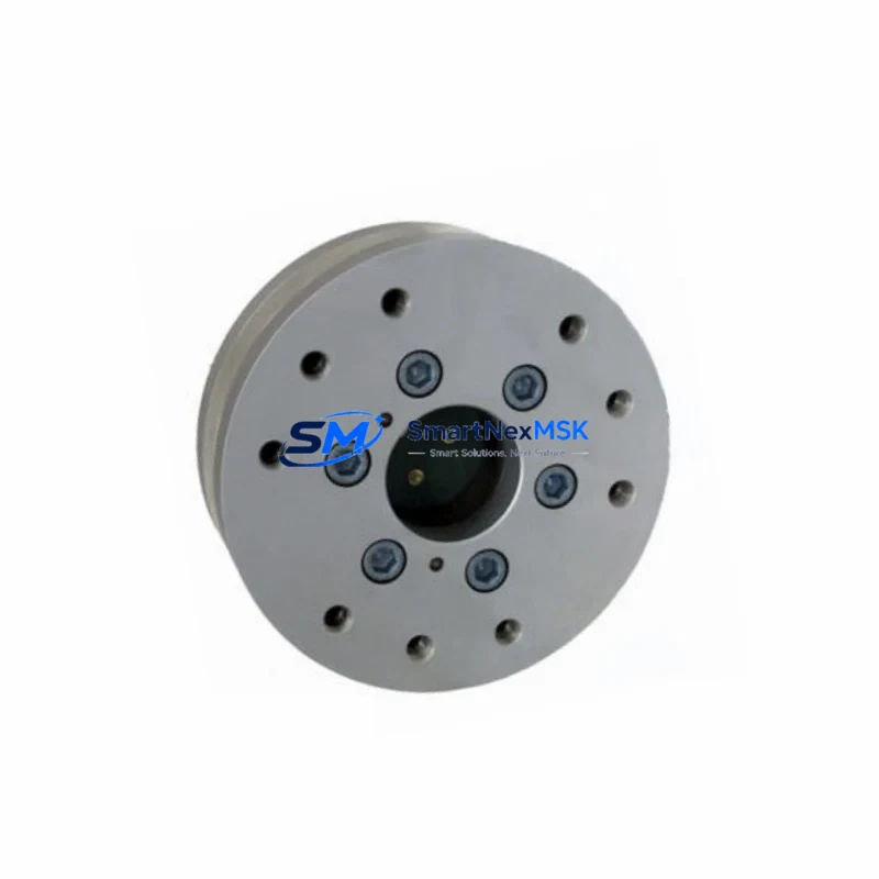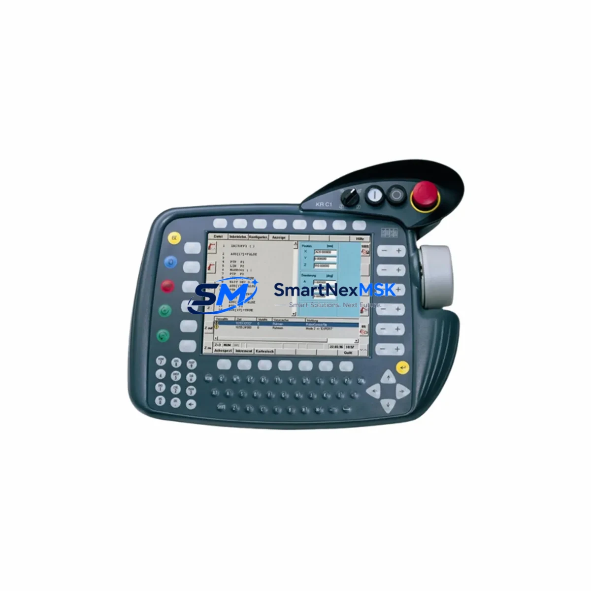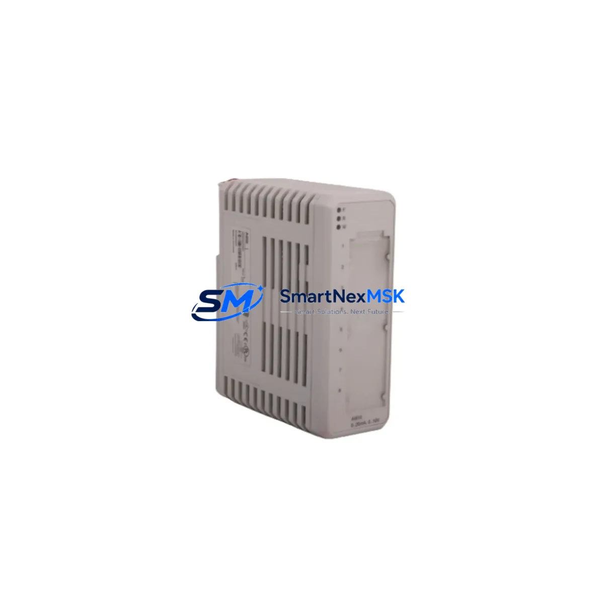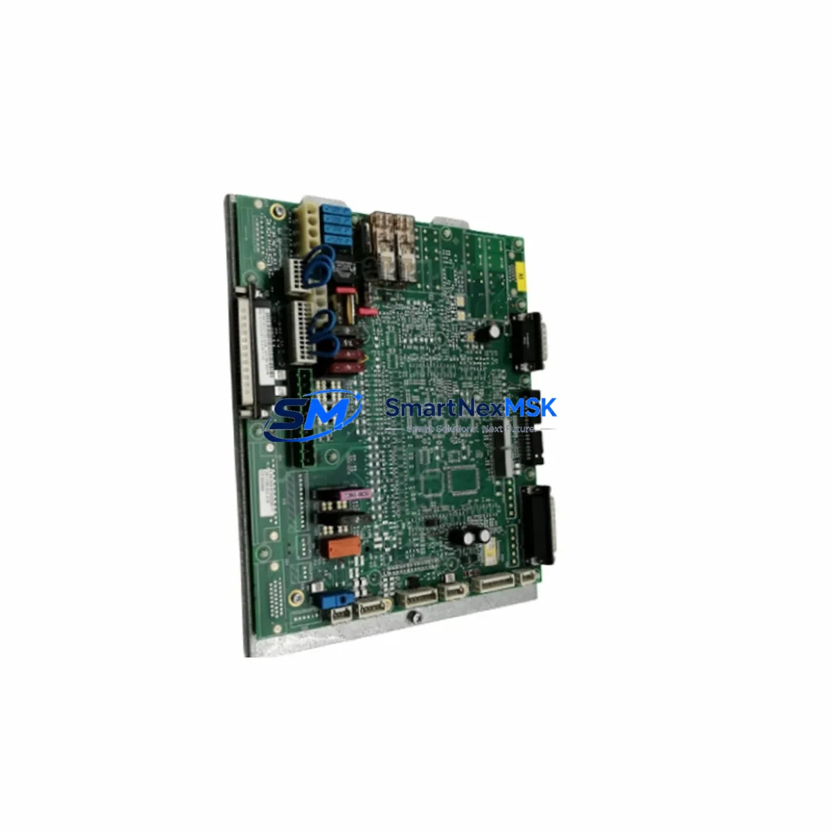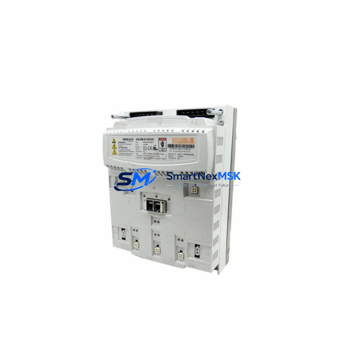
KUKA 00-245-213 Maintenance-Ready Spare for KSP 600 Automation
The KUKA 00-245-213 (KSP 600-3X20) is a 3-axis servo power module designed for KUKA KR C4 robot controller cabinets. As a critical drive component within the KSP 600 series, this module governs axis-level power distribution and servo feedback for industrial robot arms operating in continuous-duty manufacturing environments. When this module fails or degrades, the entire robot cell faces unplanned downtime — making rapid spare parts availability a top priority for maintenance engineers and procurement teams alike.
Sourced as an original KUKA spare, the 00-245-213 is tested prior to shipment and backed by a 12-month warranty. It is stocked for immediate dispatch to minimize mean time to repair (MTTR) in automotive, metal fabrication, electronics assembly, and general industrial automation facilities.
Spare Maintenance Table
| Parameter | Specification |
|---|---|
| Part Number | 00-245-213 |
| Model | KSP 600-3X20 |
| Brand | KUKA |
| Series | KSP 600 |
| Compatible Controller | KUKA KR C4 |
| Module Type | 3-Axis Servo Power Module |
| Rated Current per Axis | 20 A (3 × 20 A) |
| Supply Voltage | DC Bus (KR C4 internal) |
| Cooling | Forced air (cabinet-integrated) |
| Mounting | DIN rail / backplane slot, KR C4 cabinet |
| Origin | Germany |
| Application Environment | Industrial robot controller cabinet, IP54 enclosure |
| Compatibility | KR C4, KR C4 compact, KR C4 smallsize |
| Condition | Original spare, pre-shipment tested |
| Warranty | 12 Months |
| Weight | Approx. 1,040 g |
Maintenance Planning for Continuous Operation
When a KSP 600-3X20 servo module is flagged for replacement during a scheduled inspection or emergency fault response, experienced maintenance engineers know that the servo drive is rarely the only component requiring attention. A thorough cabinet inspection should accompany any KSP 600 swap to prevent repeat failures and ensure system stability.
Begin by verifying the KPS 600 power supply module — the primary DC bus source feeding the KSP 600-3X20. A degraded KPS 600 can cause undervoltage faults that mimic servo drive failure. Simultaneously, inspect the KCB (KUKA Controller Bus) communication board for loose connectors or firmware mismatches, as axis communication errors often accompany drive replacements in aging KR C4 systems.
Check all resolver and encoder feedback cables routed from the robot arm to the KSP module. Damaged shielding or corroded M12 connectors are a common root cause of axis position errors that trigger false drive faults. The RDC (Resolver Digital Converter) board inside the controller should also be inspected for signal integrity, particularly on high-cycle axes.
For cabinet-level electrical integrity, inspect the 24 VDC control power supply (typically a SITOP or equivalent unit) that powers the KR C4 logic circuits. Voltage sags on the 24 V rail can corrupt drive initialization sequences. Review the main contactor and pre-charge circuit for contact wear — a worn contactor can cause intermittent DC bus faults that stress the KSP module prematurely.
On the I/O side, verify the KR C4 I/O module (such as the KUKA KIO or EtherCAT I/O slave) for any error flags related to safety inputs or digital outputs connected to the drive enable chain. If the robot uses a KUKA smartPAD or KCP4 teach pendant, confirm the pendant cable and connector are undamaged, as pendant communication faults can prevent drive re-enabling after a module swap.
For systems integrated with external PLCs or safety controllers, check the ProfiSafe or EtherNet/IP safety interface configuration to ensure the new KSP module is recognized correctly by the safety network. Finally, inspect cabinet ventilation filters and fan units — thermal stress is a leading cause of premature servo module failure in high-ambient-temperature environments.
Stocking a KSP 600-3X20 alongside a KPS 600 power supply, a spare RDC board, and a set of feedback cable assemblies gives maintenance teams a complete first-response kit for KR C4 drive-related downtime events.
Site Replacement Workflow
Step 1 — Fault Isolation: Record all active fault codes from the KUKA smartPAD before powering down. Note axis-specific error codes (e.g., A1–A6) to confirm the KSP 600-3X20 is the failed component and not an upstream power or feedback issue.
Step 2 — Safe Shutdown: Execute a controlled E-stop, discharge the DC bus (wait for the KR C4 discharge indicator to clear), and lock out / tag out (LOTO) the main supply. Confirm zero voltage on the DC bus terminals before opening the cabinet.
Step 3 — Module Removal: Disconnect the DC bus bar connectors, motor power connectors (U/V/W per axis), and the KCB ribbon or fiber-optic communication link. Note cable routing and label all connectors before removal to prevent miswiring during reinstallation.
Step 4 — Install 00-245-213 Replacement: Seat the new KSP 600-3X20 into the backplane slot, reconnect all power and signal connectors in reverse order, and verify torque on bus bar bolts per KUKA service documentation. Confirm the module firmware version is compatible with the installed KR C4 software release.
Step 5 — Commissioning Check: Power up the controller, clear fault memory, and run a mastering check on all axes. Perform a slow-speed test cycle before returning the robot to production speed. Log the replacement in the maintenance record with the new module serial number and warranty start date.
This workflow is compatible with KR C4, KR C4 compact, and KR C4 smallsize variants, ensuring the 00-245-213 can serve as a direct drop-in replacement across the KR C4 platform family without software reconfiguration in most installations.
Spare Parts Support FAQ
Q1: Is the KUKA 00-245-213 compatible with all KR C4 controller variants?
The KSP 600-3X20 (00-245-213) is designed for the standard KR C4 platform and is also compatible with KR C4 compact and KR C4 smallsize cabinets. Always verify the controller’s KSP slot configuration and firmware version before installation. If your system uses a KR C4 extended or a customized OEM cabinet, contact our technical team for compatibility confirmation prior to ordering.
Q2: How is the module tested before shipment?
Each 00-245-213 unit undergoes functional verification including DC bus interface checks, communication link validation, and visual inspection for physical damage before dispatch. Units are packed in anti-static ESD-safe packaging with foam cushioning to prevent transit damage. A test report is available upon request for quality-critical procurement processes.
Q3: What does the 12-month warranty cover?
The 12-month warranty covers manufacturing defects and functional failures under normal operating conditions. It does not cover damage caused by incorrect installation, overvoltage events, liquid ingress, or physical impact. Warranty claims are processed with return of the defective unit; replacement or repair is completed within the agreed lead time. Warranty period begins from the date of shipment.
Q4: Can you support long-term or blanket stock orders for this part?
Yes. For facilities managing multiple KR C4 robot cells or planning extended maintenance contracts, we support scheduled delivery agreements and reserved stock arrangements for the 00-245-213. Long-term supply planning helps avoid critical shortages during KUKA end-of-life (EOL) transitions for the KSP 600 series. Contact our sales team to discuss volume pricing and consignment stock options.
© 2026 SMARTNEXMSK. All rights reserved.
Original Source: https://smartnexmsk.com
Contact: [email protected] | +86 18259474341