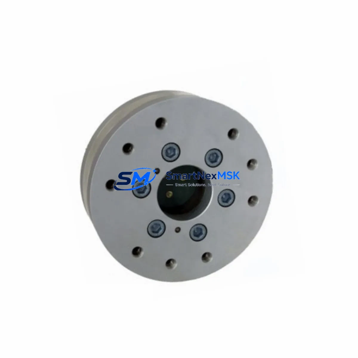
KUKA 00-287-202-9105-ECAT-AXlA80-ZD1 Retrofit-Ready Precision Gearbox for ECAT AXlA80 Control Systems
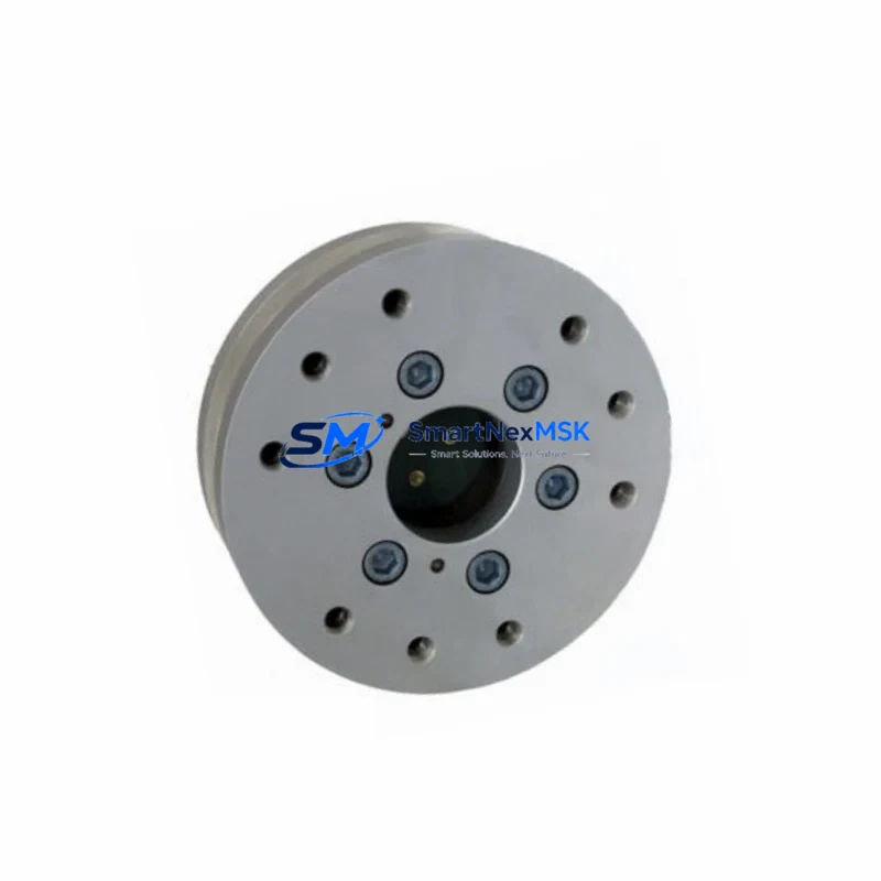
The KUKA 00-287-202-9105-ECAT-AXlA80-ZD1 is a precision gearbox engineered for seamless integration into KUKA ECAT AXlA80 ZD1 series robotic and automation control systems. As legacy KUKA drive train components reach end-of-life or become increasingly difficult to source, this unit provides a verified retrofit solution that preserves mechanical interfaces, output torque ratings, and positional accuracy without requiring structural modifications to the robot arm or control cabinet. Whether you are managing a planned upgrade cycle or responding to an unplanned gearbox failure on the production floor, the 00-287-202-9105-ECAT-AXlA80-ZD1 is designed to minimize engineering risk and reduce total downtime.
This gearbox is commonly deployed in axis-level replacements across KUKA KR series industrial robots, where the ECAT AXlA80 drive module governs joint motion through EtherCAT-based servo communication. Technicians performing the swap must verify the output flange bolt pattern, shaft diameter, and gear ratio against the original specification sheet before installation. The mounting interface on the AXlA80 ZD1 variant is dimensionally consistent with earlier ZD0 configurations in most axis positions, though torque preload settings in the KRC4 or KRC5 controller may require recalibration via WorkVisual after the replacement is complete.
Upgrade Compatibility Table
| Parameter | Details |
|---|---|
| Compatible Series | KUKA ECAT AXlA80 ZD1, ZD0 (axis-dependent) |
| Mounting Interface | Standard AXlA80 flange pattern; verify bolt circle diameter before installation |
| Communication Compatibility | EtherCAT (ECAT) servo protocol; compatible with KRC4 / KRC5 controller platforms |
| Installation Requirement | Torque preload recalibration via WorkVisual required post-swap |
| Replacement Recommendation | Direct drop-in for worn or failed AXlA80 ZD1 gearbox units; no structural modification required |
| Commissioning Focus | Zero-point mastering, axis mastering via KUKA smartPAD, and load data verification |
| Warranty | 12-Month Warranty — covers manufacturing defects and functional failure under normal operating conditions |
Retrofit Planning for Existing Automation Systems
A successful gearbox retrofit on a KUKA robot begins well before the maintenance window opens. Engineers should pull the robot’s axis load data from the KRC4 or KRC5 controller and cross-reference the rated input torque of the 00-287-202-9105-ECAT-AXlA80-ZD1 against the actual duty cycle logged in the system. If the robot has been operating near its rated payload for extended periods, adjacent components such as the KUKA KPP 600-20 servo power pack and the KSP 600-3×40 servo drive module should be inspected simultaneously, as gearbox wear is often accompanied by increased current draw at the drive level.
During disassembly, technicians should document the existing wiring harness routing at the axis connector block. The ECAT AXlA80 motor resolver cable and the brake release line must be carefully labeled before disconnection. Replacement of the gearbox does not require modification of the motor itself, but the motor-to-gearbox coupling must be inspected for fretting wear. If the coupling shows signs of micro-movement damage, it should be replaced alongside the gearbox to prevent premature failure of the new unit.
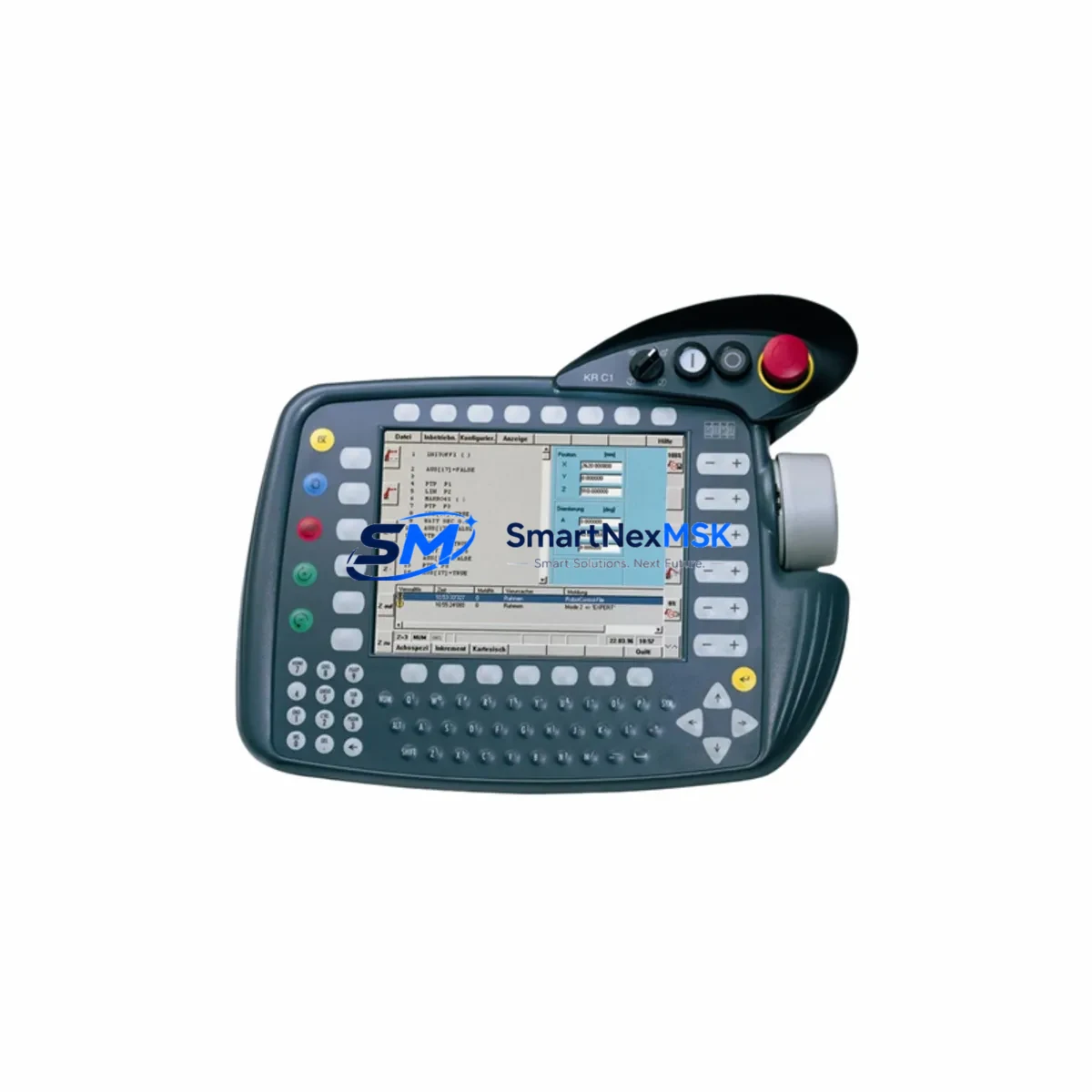
For systems running older KRC2 controllers that have been upgraded to KRC4 via a KUKA Sunrise Cabinet migration, the EtherCAT network topology must be verified after the gearbox swap. The KUKA KM 40 EtherCAT junction and any intermediate KUKA CCU (Cabinet Control Unit) nodes should be checked for correct slave addressing. If the robot cell includes a KUKA KR C4 smartPAD-2 HMI panel, the axis mastering procedure must be performed using the electronic mastering device (EMD) to restore accurate joint position data. Skipping this step will result in incorrect TCP (Tool Center Point) positioning and may trigger safety zone violations in the cell controller.
In multi-robot cells where a KUKA KR AGILUS or KR QUANTEC shares a common safety PLC — such as a Pilz PNOZ or a Siemens ET 200SP safety module — the safety configuration must be re-validated after any axis-level hardware change. The safety controller’s robot signature or CRC checksum may be invalidated by the maintenance event, requiring a re-acceptance test before the cell can return to automatic mode. Planning for this validation step is critical to accurate downtime estimation.
Facilities that maintain a KUKA.RoboTeam or multi-arm coordinated motion setup should also verify that the motion synchronization parameters stored in the WorkVisual project file remain consistent after the gearbox replacement. Any change in axis stiffness or backlash characteristics — even within specification — can affect coordinated path accuracy and should be validated with a test cycle before resuming production.
Downtime Control During System Migration
Minimizing unplanned downtime during a gearbox replacement requires a structured pre-staging approach. Before the maintenance window begins, the replacement 00-287-202-9105-ECAT-AXlA80-ZD1 unit should be inspected for shipping damage, and the gear ratio and flange dimensions should be physically verified against the original part. Having the correct KUKA grease — typically Optifluid ZS or the specified lubricant listed in the robot’s maintenance manual — pre-measured and ready will eliminate delays during reassembly.
The robot program should be backed up from the KRC controller to an external USB drive or network share before any mechanical work begins. This backup preserves the SRC program files, the machine data configuration, and the current mastering offsets. If the controller is a KRC4 with a KUKA.SafeOperation package active, the safe axis ranges and safe speed limits stored in the safety configuration must also be exported and documented.
After the new gearbox is installed and the motor coupling is torqued to specification, the axis mastering sequence should be performed in the following order: load the robot to its reference payload, move the axis to the pre-mastering position using the smartPAD, attach the EMD to the mastering socket, and record the new mastering value in WorkVisual. Once mastering is complete, run a slow-speed verification cycle through the full axis range to confirm smooth motion and absence of abnormal noise or vibration. Only after this verification should the robot be returned to automatic mode and production speed.
For facilities with strict OEE (Overall Equipment Effectiveness) targets, pre-positioning a spare KUKA KPP servo power pack and a tested spare KSP drive module in the control cabinet before the maintenance window can further reduce risk. If a drive fault occurs during the post-replacement commissioning cycle, having these components on hand eliminates the need for an emergency procurement event that could extend the outage by days.
Retrofit Support FAQ
Q1: Is the 00-287-202-9105-ECAT-AXlA80-ZD1 a direct replacement for the original KUKA AXlA80 ZD1 gearbox?
Yes. This unit is a verified retrofit replacement for the KUKA ECAT AXlA80 ZD1 gearbox. The mechanical interface, flange pattern, and gear ratio are consistent with the original specification. Post-installation axis mastering via WorkVisual is required to restore positional accuracy.
Q2: What commissioning steps are required after installation?
After mechanical installation and motor coupling torque verification, perform axis mastering using the KUKA EMD and smartPAD. Recalibrate torque preload settings in the KRC4 or KRC5 controller via WorkVisual. Run a slow-speed verification cycle through the full axis range before returning the robot to automatic mode. If KUKA.SafeOperation is active, re-validate the safety configuration.
Q3: How is the unit tested before shipment?
Each 00-287-202-9105-ECAT-AXlA80-ZD1 unit undergoes outgoing inspection including dimensional verification of the output flange, gear backlash measurement, and rotational smoothness testing. Units are packed with protective end caps and anti-vibration foam to prevent transit damage. A test report is available upon request.
Q4: What does the 12-month warranty cover?
The 12-month warranty covers manufacturing defects and functional failure under normal operating conditions from the date of shipment. It does not cover damage resulting from improper installation, incorrect lubrication, operation beyond rated load, or physical impact. Warranty claims are supported by our technical team at [email protected].
© 2026 SMARTNEXMSK. All rights reserved.
Original Source: https://smartnexmsk.com
Contact: [email protected] | +86 18259474341