KUKA MFC2-IC3 00-125-236 Spare for KRC2 Automation
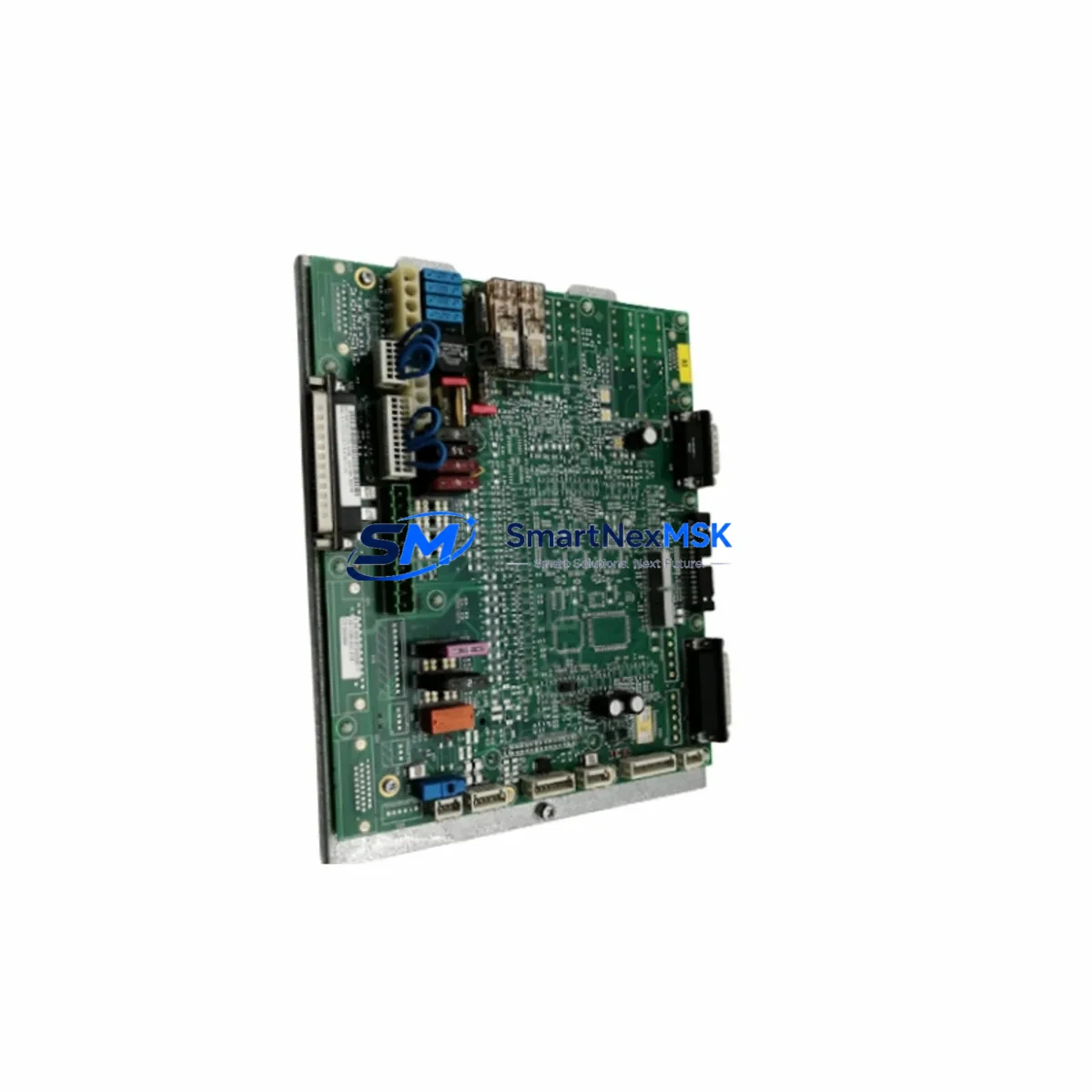
The KUKA MFC2-IC3 (part numbers 00-125-236 / 00-108-766) is the multi-function controller board at the heart of the KRC2 robot controller cabinet. As the primary interface between the robot’s motion control, I/O processing, and fieldbus communication layers, this board is a critical single point of failure in any KRC2-based production cell. When it fails, the entire robot axis goes offline — making a verified, tested spare unit the most cost-effective insurance against unplanned downtime.
This listing supplies an original KUKA MFC2-IC3 board, sourced from decommissioned KRC2 cabinets and fully tested under load prior to shipment. Each unit is inspected for capacitor health, connector integrity, firmware compatibility, and communication bus function. A 12-month warranty is included on every unit shipped.
Spare Maintenance Table
| Parameter | Specification |
|---|---|
| Part Number | 00-125-236 / 00-108-766 |
| Model | MFC2-IC3 |
| Compatible Controller | KUKA KRC2 (all variants incl. KRC2 ed05) |
| Board Function | Multi-Function Controller — motion, I/O, fieldbus coordination |
| Communication Interfaces | INTERBUS, DeviceNet, PROFIBUS DP (firmware-dependent) |
| Operating Voltage | 24 VDC (supplied via KRC2 internal PSU) |
| Operating Temperature | 0 °C to +55 °C |
| Mounting | Direct backplane slot in KRC2 controller cabinet |
| Firmware | Compatible with KSS 4.x / 5.x series |
| Condition | Original, tested, fully functional |
| Origin | Germany |
| Weight | 850 g (approx.) |
| Warranty | 12 Months |
| Application | Automotive, general manufacturing, palletizing, welding cells |
| Maintenance Recommendation | Replace at first sign of axis fault, E-stop loop failure, or fieldbus dropout |
Maintenance Planning for Continuous Operation
Maintenance engineers working on KRC2 robot cells know that the MFC2-IC3 rarely fails in isolation. A board-level fault is often preceded — or accompanied — by stress on adjacent components in the same controller cabinet. When planning a replacement of the MFC2-IC3, a thorough inspection of the following components is strongly recommended to prevent repeat failures and ensure a clean return to service:
Begin with the KRC2 power supply unit (PSU): a degraded PSU delivering unstable 24 VDC rail voltage is one of the leading causes of MFC2 board damage. Measure output voltage under load before installing the replacement board. Next, inspect the KPS600 or KPS1500 servo power supply — ripple or transient spikes from the drive bus can propagate back through the cabinet and stress controller logic boards.
Check all X11 and X13 safety interface connectors on the KRC2 cabinet. Corroded or loose pins in the E-stop chain and safety gate circuits frequently generate fault codes that are misdiagnosed as MFC2 failures. Similarly, inspect the RDC (Resolver-to-Digital Converter) board mounted on the robot arm — a failing RDC produces axis position errors that can trigger MFC2 watchdog resets.
For cells using fieldbus communication, verify the PROFIBUS DP or DeviceNet interface module seated on the MFC2 board itself. These plug-in communication cards (e.g., KUKA PROFIBUS slave card) are separate serviceable items and should be transferred carefully during board swap. Inspect the KRC2 fan assembly and filter mats: thermal stress from blocked airflow is a primary accelerant of PCB component aging on the MFC2.
On the teach pendant side, confirm the KCP2 (KUKA Control Panel) cable and connector are undamaged — a shorted KCP2 cable can load the MFC2 communication bus and cause intermittent faults. If the cell uses external I/O, inspect the terminal block wiring (X20/X21 I/O connectors) for loose terminations that may have caused the original fault condition. For older KRC2 ed05 cabinets, also check the CI3 board (Customer Interface 3) for relay contact wear, as this board works in close coordination with the MFC2 for safety and I/O routing.
Finally, if the robot is part of a multi-robot cell, verify the inter-robot communication cabling and any signal isolators on shared I/O lines — ground loops between cabinets are a known source of MFC2 board stress in high-density welding and assembly lines.
Site Replacement Workflow
Step 1 — Isolate and document: Power down the KRC2 cabinet via the main isolator. Photograph the existing MFC2-IC3 board position, all connected cables, and any fieldbus plug-in cards before removal. Note the firmware version displayed on the KCP2 pendant prior to shutdown.
Step 2 — Remove the failed board: Release the board retention clips and carefully extract the MFC2-IC3 from its backplane slot. Transfer any plug-in fieldbus communication cards to the replacement board, ensuring correct seating.
Step 3 — Install the replacement: Seat the new MFC2-IC3 firmly into the backplane slot. Reconnect all cables in the documented order. Verify that the 24 VDC supply connector is fully engaged.
Step 4 — Power-up and verify: Apply power and observe the KCP2 pendant boot sequence. Confirm that the KSS software version matches the previous installation. Run a cold start and verify all axes initialize without fault. Execute a short manual jog cycle on each axis to confirm motion control integrity.
Step 5 — Fieldbus re-commissioning: If the cell uses PROFIBUS or DeviceNet, verify that the network master recognizes the robot node and that all I/O signals are mapped correctly. A brief I/O force test is recommended before returning the cell to automatic mode.
This workflow minimizes downtime to under two hours for a prepared maintenance team with a tested spare unit on hand — compared to days or weeks waiting for OEM repair or new supply. Stocking one verified MFC2-IC3 spare per two to three KRC2 robots is a widely adopted strategy in automotive and general manufacturing environments.
Spare Parts Support FAQ
Q1: Is this MFC2-IC3 compatible with both 00-125-236 and 00-108-766 part numbers?
Yes. The MFC2-IC3 was produced under both part numbers across different production batches. Both numbers refer to functionally equivalent boards for the KRC2 controller. Always verify the KSS firmware version on your controller before installation to ensure compatibility.
Q2: How is each unit tested before shipment?
Every MFC2-IC3 board is bench-tested in a live KRC2 controller environment. Tests include power-on self-test completion, axis communication verification, fieldbus interface check, and I/O signal routing confirmation. Units that fail any test stage are not listed for sale. A test report is available on request.
Q3: What does the 12-month warranty cover?
The warranty covers all functional defects arising from normal use in a KRC2 controller environment. It does not cover damage caused by incorrect installation, overvoltage events, or physical mishandling. In the event of a warranty claim, we provide a replacement unit or full refund after fault verification.
Q4: Can you support long-term spare parts supply for legacy KRC2 fleets?
Yes. We maintain ongoing stock of MFC2-IC3 boards and related KRC2 components to support production facilities running legacy robot fleets beyond OEM support windows. Volume pricing and reserved stock agreements are available for maintenance departments managing five or more KRC2 controllers. Contact us to discuss a tailored supply arrangement.
© 2026 SMARTNEXMSK. All rights reserved.
Original Source: https://smartnexmsk.com
Contact: [email protected] | +86 18259474341