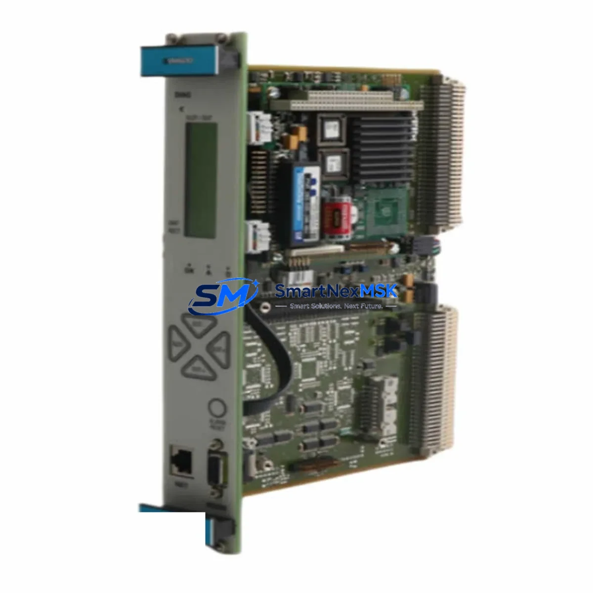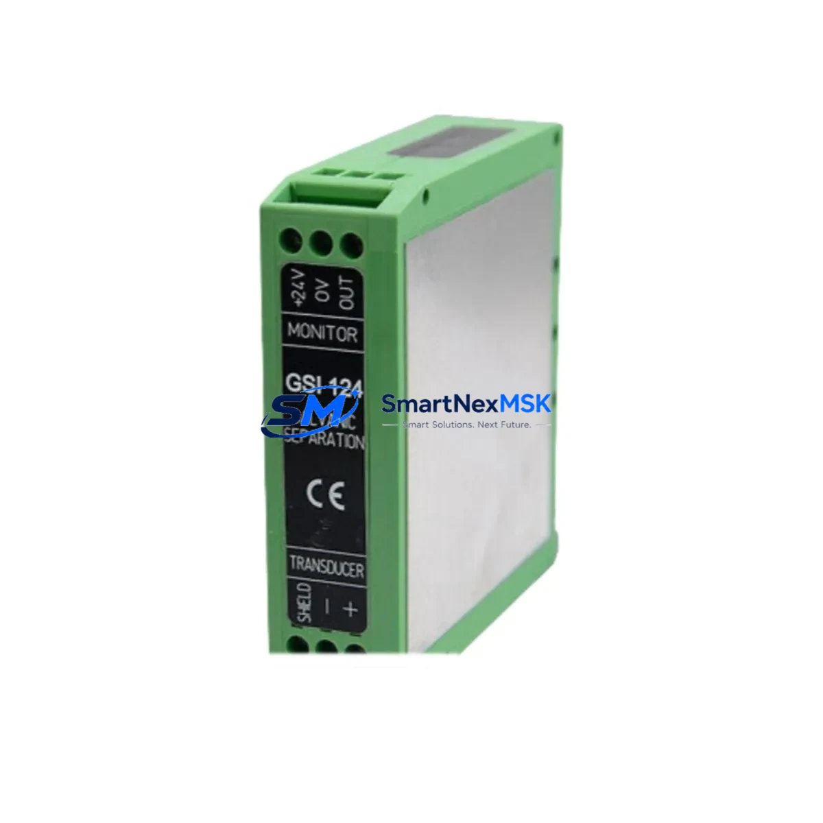
Meggitt GSI124-244-124-000-021 Retrofit-Ready Vibration Sensor for GSI Series Control Systems
The Meggitt GSI124-244-124-000-021 is a precision vibration sensor engineered for seamless integration into existing GSI Series condition monitoring and machinery protection systems. As legacy vibration monitoring platforms reach end-of-life or face discontinued spare parts availability, the GSI124-244-124-000-021 provides a verified retrofit path that preserves original signal conditioning architecture, terminal wiring layouts, and system calibration parameters — minimizing engineering rework and unplanned downtime during replacement campaigns.
Manufactured by VIBRO METER, a Meggitt brand with decades of heritage in turbomachinery and rotating equipment protection, this sensor is designed to interface directly with existing GSI Series signal conditioners, barrier modules, and monitoring racks without requiring firmware changes or hardware adapters. For facilities managing aging turbine protection panels, compressor monitoring cabinets, or pump condition monitoring loops, the GSI124-244-124-000-021 represents a cost-effective, technically sound upgrade over sourcing obsolete OEM spares.
Upgrade Compatibility Table
| Parameter | Details |
|---|---|
| SKU / Part Number | GSI124-244-124-000-021 |
| Brand / Manufacturer | VIBRO METER (Meggitt) |
| Product Series | GSI Series |
| Product Type | Vibration Sensor (Accelerometer / Velocity Transducer) |
| Mounting Interface | Compatible with standard GSI Series mounting threads and flange configurations |
| Electrical Interface | Drop-in terminal wiring compatible with GSI Series signal conditioners and barrier modules |
| Communication / Signal | Analog output (4–20 mA / voltage), compatible with existing GSI Series monitoring racks |
| Replacement Suitability | Direct replacement for discontinued GSI Series vibration sensor variants |
| Commissioning Notes | Verify sensitivity scaling, zero-offset calibration, and alarm setpoints in monitoring software after installation |
| Warranty | 12-Month Warranty — covers manufacturing defects under normal operating conditions |
| Origin | Switzerland (CH) |
| Shipping | Fast global shipping from Xiamen; export documentation available on request |
Retrofit Planning for Existing Automation Systems
Replacing a vibration sensor in an active machinery protection loop requires careful pre-planning to avoid inadvertent trips or loss of monitoring coverage. Before removing the legacy unit, engineers should document the existing terminal wiring scheme — including shield grounding points, cable routing through the junction box, and the barrier module or intrinsic safety isolator in use. The GSI124-244-124-000-021 is designed to match the connector pinout and cable entry configuration of the original GSI Series sensor, reducing the need for field wiring modifications.
In a typical GSI Series retrofit scenario, the sensor interfaces with a VM600 series rack-mounted monitoring system or equivalent VIBRO METER signal processing hardware. The rack may house multiple channel cards — such as the MPC4 machinery protection card or the IOC4T I/O card — which receive the raw vibration signal and apply configured alarm thresholds. During replacement, it is critical to confirm that the new sensor’s sensitivity (expressed in mV/g or mV/mm·s⁻¹) matches the scaling factor programmed into the channel card, otherwise alarm setpoints will be offset and protection logic may be compromised.
For facilities running integrated condition monitoring platforms, the sensor replacement should be coordinated with a review of the associated proximitor or signal conditioner — for example, the VM600 RPSM power supply module or the MPC4 protection card — to ensure the excitation voltage and bias current supplied to the sensor remain within specification. If the control cabinet also houses a Bently Nevada 3500 series rack or a Emerson CSI 6500 machinery health monitor in a parallel monitoring role, cross-channel alarm logic should be reviewed before the new sensor is brought online.
Where the existing system uses a fieldbus or digital communication backbone — such as Modbus RTU over RS-485, PROFIBUS DP, or a 4–20 mA HART loop — the replacement sensor’s analog output must be verified against the input range configured in the DCS or PLC. In plants running Siemens SIMATIC S7-300 or S7-400 series controllers with analog input modules (such as the SM 331 or SM 334), the engineering unit scaling in the hardware configuration tool (HW Config / TIA Portal) should be checked to confirm the new sensor’s output range is correctly mapped. Similarly, for ABB AC800M or Honeywell Experion PKS-based systems, the I/O assignment and tag database should be updated to reflect any sensitivity changes.
Facilities managing multiple rotating assets — including steam turbines, gas compressors, cooling tower fans, and boiler feed pumps — often maintain a standardized spare parts inventory that includes vibration sensors, proximity probes, cable assemblies, and terminal blocks. The GSI124-244-124-000-021 is stocked to support rapid deployment in these multi-asset environments, with pre-shipment functional testing and calibration documentation available upon request.
Downtime Control During System Migration
Minimizing production downtime during a vibration sensor replacement requires a structured hot-swap or planned-outage strategy. For non-redundant monitoring loops, the preferred approach is to schedule the replacement during a planned maintenance window, with the protection system placed in bypass mode under a formal Management of Change (MOC) procedure. The bypass should be time-limited, with a designated engineer on-site to monitor the machine manually during the sensor exchange.
Where the monitoring system supports channel inhibit or bypass functions — as is standard in VM600 rack systems and most Bently Nevada 3500 series configurations — the affected channel should be inhibited at the rack level before disconnecting the field wiring. This prevents a spurious trip signal from propagating to the emergency shutdown system (ESD) or the distributed control system (DCS) during the wiring changeover. After the GSI124-244-124-000-021 is installed and the terminal connections are verified against the as-built wiring diagram, the channel inhibit should be released and the sensor output confirmed against the expected baseline vibration level before the bypass is lifted.
For facilities with redundant sensor configurations — where two sensors monitor the same measurement plane and a voting logic (1oo2 or 2oo3) is applied — the replacement can often be performed online by removing one sensor at a time while the redundant channel maintains protection coverage. In this case, the engineering team should confirm that the monitoring system’s voting logic is correctly configured and that the remaining active channel is within its calibrated range before proceeding.
Post-installation, a functional acceptance test should be performed: apply a known vibration stimulus (using a calibration shaker or by referencing a known machine operating condition) and verify that the sensor output, alarm setpoints, and trip thresholds respond correctly. All test results should be documented and retained as part of the equipment maintenance record. SMARTNEXMSK provides pre-shipment test reports for the GSI124-244-124-000-021 to support site acceptance testing and reduce commissioning time.
Retrofit Support FAQ
Q1: Is the GSI124-244-124-000-021 a direct drop-in replacement for the original GSI Series vibration sensor?
A: Yes, the GSI124-244-124-000-021 is designed as a form-fit-function replacement for the corresponding GSI Series sensor variant. The mechanical mounting interface, terminal wiring layout, and signal output characteristics are matched to the original specification. Minor sensitivity calibration verification is recommended after installation to confirm alignment with the programmed alarm setpoints in the monitoring rack.
Q2: What commissioning steps are required after installing the GSI124-244-124-000-021?
A: After mechanical installation and terminal wiring, verify the sensor bias voltage at the signal conditioner input, confirm the output signal level against a known reference, and check that the alarm and trip setpoints in the monitoring system (e.g., VM600 rack, Bently Nevada 3500, or equivalent) correspond to the new sensor’s sensitivity. Update the maintenance record and retain the pre-shipment test report for traceability.
Q3: Does SMARTNEXMSK provide wiring diagrams or technical documentation for the GSI124-244-124-000-021?
A: Yes. Technical datasheets, terminal wiring diagrams, and pre-shipment functional test reports are available upon request. Contact our technical team at [email protected] to request documentation prior to or alongside your order.
Q4: What warranty coverage applies to the GSI124-244-124-000-021?
A: All units are covered by a 12-Month Warranty against manufacturing defects under normal operating conditions. The warranty covers sensor output failure, connector integrity, and mechanical housing defects. It does not cover damage resulting from incorrect installation, overvoltage, or exposure to conditions outside the rated specification. Warranty claims are processed through SMARTNEXMSK with replacement or repair turnaround coordinated to minimize site downtime.
© 2026 SMARTNEXMSK. All rights reserved.
Original Source: https://smartnexmsk.com
Contact: [email protected] | +86 18259474341