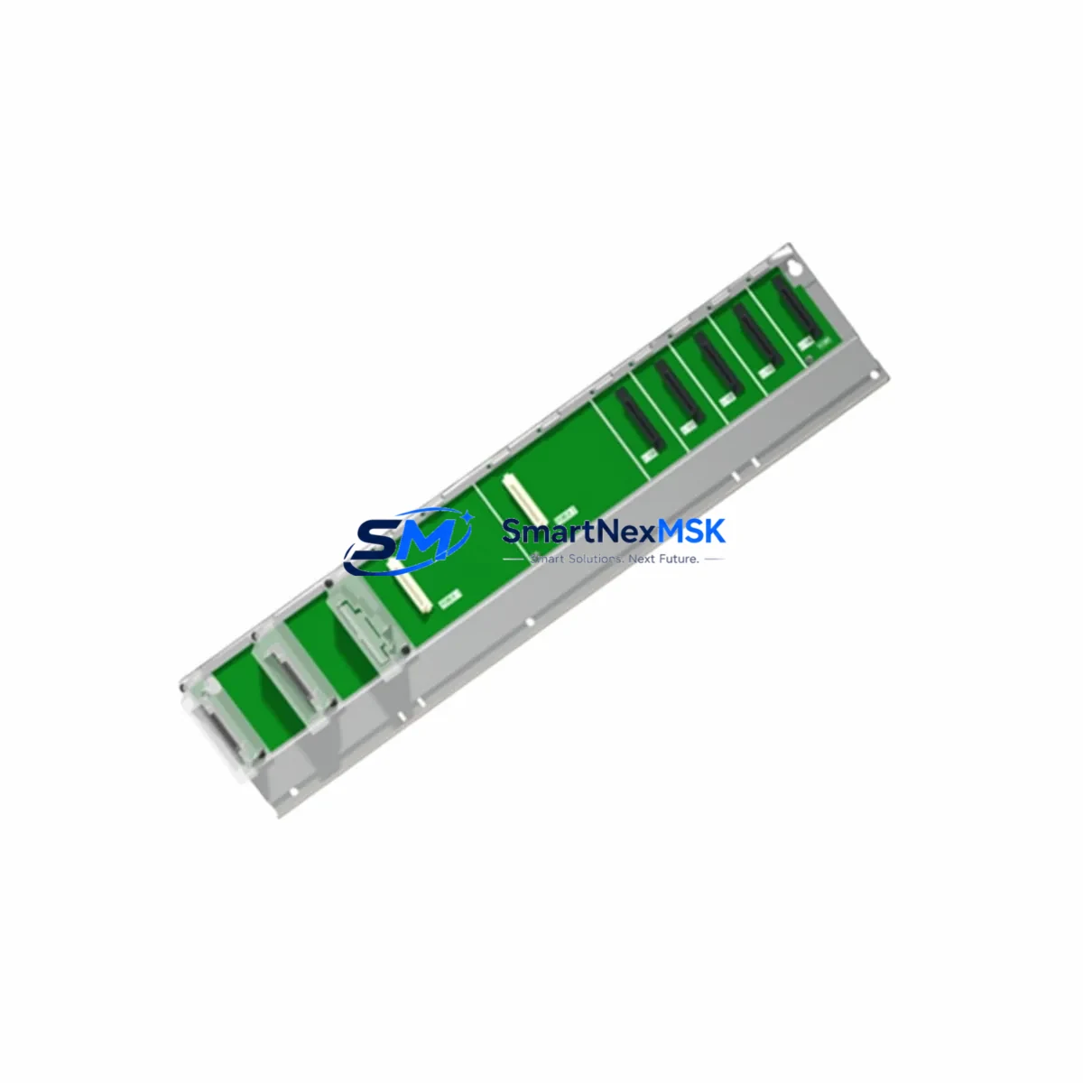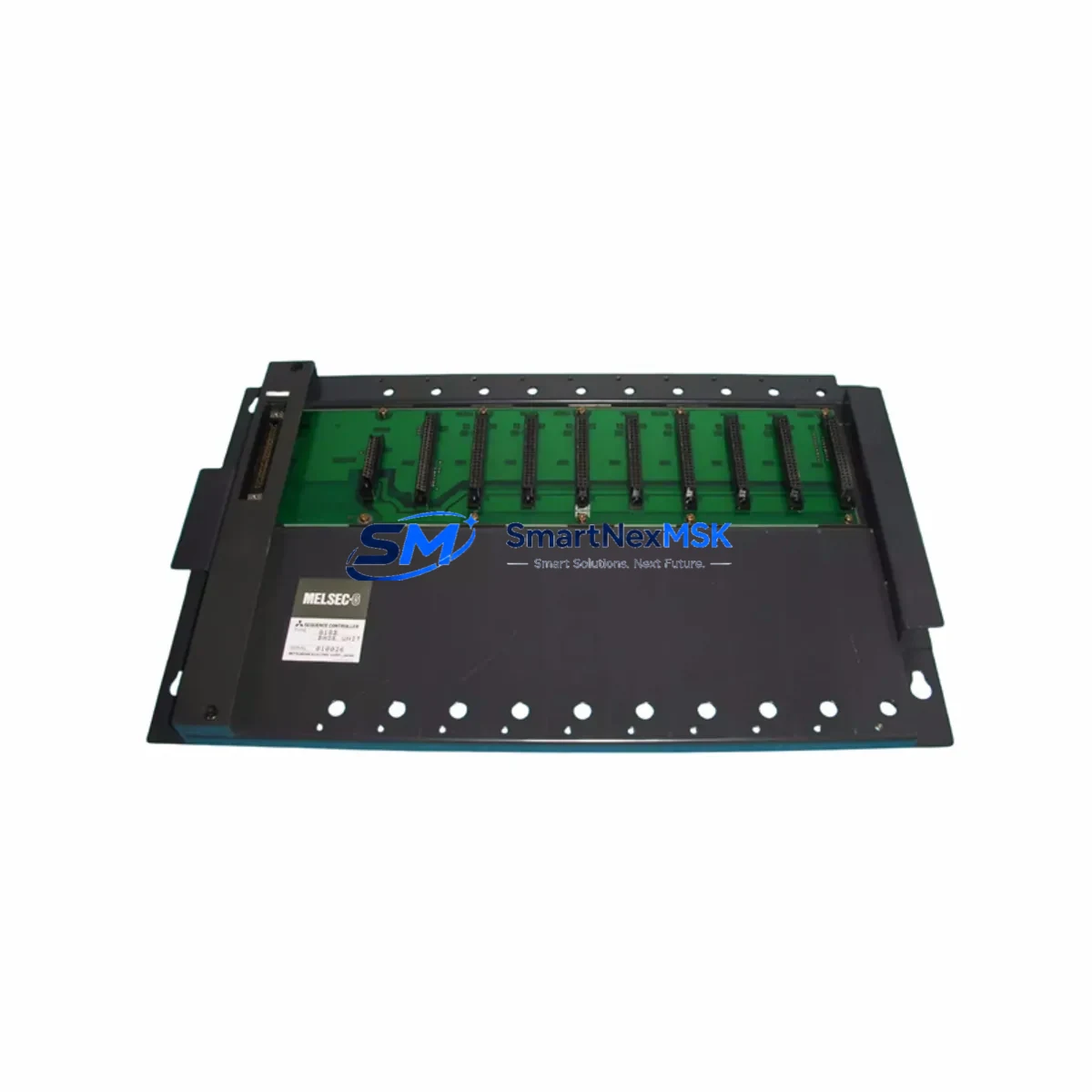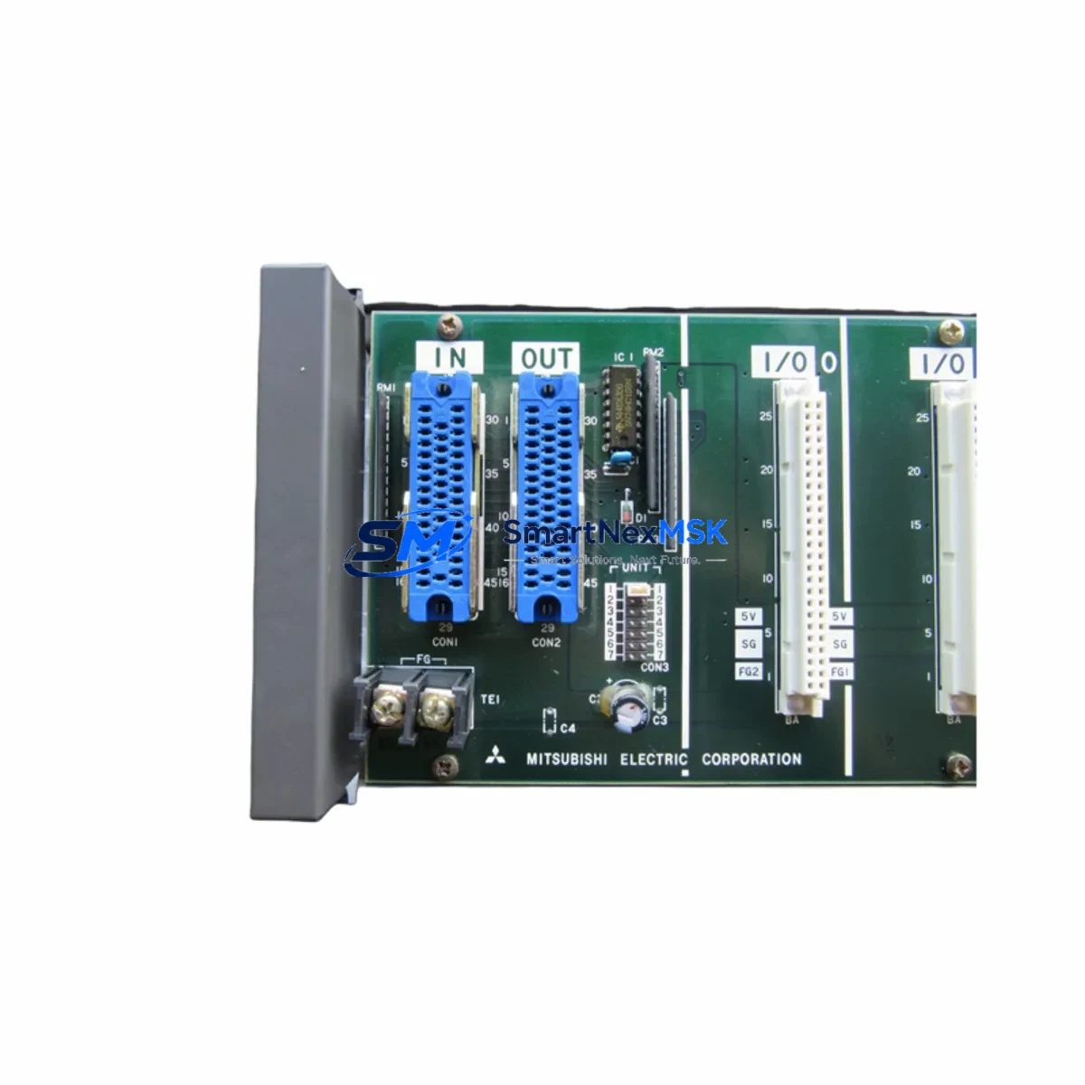
Mitsubishi BD625A988G52 A58B Retrofit-Ready Base Unit for MELSEC A-Series Control Systems
The Mitsubishi BD625A988G52 A58B is an 8-slot backplane base unit engineered for the MELSEC A-Series programmable logic controller platform. As legacy A-Series installations reach end-of-life and original Mitsubishi Electric spare parts become increasingly scarce, the BD625A988G52 A58B serves as a verified retrofit-ready replacement that preserves existing rack geometry, module slot assignments, and backplane bus architecture — enabling engineers to restore or upgrade aging control systems without redesigning the entire control cabinet.
This base unit supports the full range of A-Series I/O modules, CPU units, and communication modules that were originally installed in MELSEC A-Series racks. Whether you are replacing a failed backplane in a running production line or executing a planned modernization of a legacy DCS-linked control cabinet, the BD625A988G52 A58B provides the mechanical and electrical foundation required for a smooth, low-risk transition.
Upgrade Compatibility Table
| Parameter | BD625A988G52 A58B Specification | Retrofit Notes |
|---|---|---|
| Slot Count | 8 slots | Matches original A58B rack slot count; no module readdressing required if slot population is unchanged |
| Compatible CPU Modules | A2USCPU, A3UCPU, A2UCPU-S1, A1SCPU series | Verify CPU firmware revision before swap; retain original program memory backup |
| Backplane Bus | MELSEC A-Series parallel bus | Not compatible with Q-Series or iQ-R Series bus architecture without migration adapter |
| Power Supply Interface | Accepts A1S61P, A1S62P, A61P, A62P power supply modules | Confirm power supply capacity covers total module current draw after any I/O expansion |
| Communication Compatibility | Supports MELSEC-A NET, CC-Link (via dedicated comm module), RS-232C/RS-422 | Verify network module slot position matches original rack wiring and address settings |
| Installation Dimensions | Standard A-Series DIN rail / panel mount | Existing cabinet cutout and mounting holes are compatible; no mechanical modification required |
| Terminal Wiring | Backplane connector — no field wiring directly on base unit | All field wiring remains on I/O module terminal blocks; no rewiring of field cables required |
| Module Address Assignment | Slot-based addressing (slots 0–7) | Confirm GX Developer or GX Works2 I/O assignment map matches physical slot population |
| Warranty | 12-Month Warranty | Covers manufacturing defects; includes pre-shipment functional test report |
Retrofit Planning for Existing Automation Systems
Successful retrofit of the BD625A988G52 A58B into an existing MELSEC A-Series control system requires a structured pre-installation audit. Begin by documenting the current rack population: record each module type, slot position, I/O address range, and any jumper or DIP switch settings. Common modules found alongside the A58B base unit include the A1SD51S MELSECNET/MINI-S3 data link module, A1SJ71AP23Q MELSEC-A NET/10 communication module, and A68AD analog input module — all of which retain their original slot assignments when the base unit is replaced in kind.
Power budget verification is a critical step that is frequently overlooked. The A1S62P or A61P power supply module mounted on the base unit must supply sufficient current to all installed modules. Calculate the total 5 VDC and 24 VDC current consumption from each module’s specification sheet and confirm the power supply’s rated output is not exceeded. If the retrofit includes adding new I/O capacity — for example, inserting an additional A1SX40 DC input module or A1SY10 transistor output module — recalculate the power budget before finalizing the module layout.
For systems that include an A1SD61 positioning module or A273UCPU motion CPU, confirm that the base unit slot assignment for these specialty modules is preserved exactly. Motion and positioning modules are sensitive to slot address changes, and any deviation will require corresponding updates in the GX Developer project file and HMI screen tag bindings. If the plant uses a GOT1000 or GOT-A900 series HMI connected via RS-422 to the CPU, verify that the communication port settings — baud rate, station number, and protocol — are unchanged after the base unit swap.
Where the existing system uses CC-Link for distributed I/O, the A1SJ61BT11 CC-Link master module must be reinstalled in its original slot to preserve remote station addressing. Any change in the master module’s slot position will invalidate the CC-Link parameter settings stored in the CPU program and will require a full network reconfiguration using GX Configurator-CC.
For sites migrating from MELSEC A-Series to Q-Series as part of a broader modernization program, the BD625A988G52 A58B can serve as an interim replacement to restore production while the Q-Series migration is planned. The A-Q Conversion Base Unit (QA1S6□B series) is the recommended long-term migration path, but the BD625A988G52 A58B provides an immediate, cost-effective solution to eliminate unplanned downtime caused by backplane failure.
Downtime Control During System Migration
Minimizing production interruption during a base unit replacement requires preparation that begins well before the maintenance window. The following protocol is recommended for sites where continuous operation is critical:
Step 1 — Program Backup: Use GX Developer or GX Works2 to perform a full upload of the CPU program, including all parameters, device comments, and network configuration data. Store the backup on a dedicated programming cable-connected laptop and verify the backup file integrity before proceeding. The SC-09 or USB-SC09-FX programming cable is commonly used for this connection.
Step 2 — I/O Snapshot: Record the current state of all digital and analog I/O points. For analog modules such as the A68AD or A62DA, note the current channel scaling and offset values. This data is essential for verifying correct operation after the base unit swap.
Step 3 — Controlled Shutdown: Execute a controlled PLC STOP command from the programming terminal. Do not power-cycle the cabinet without first placing the CPU in STOP mode to prevent output relay chatter and protect connected field devices.
Step 4 — Module Extraction and Base Unit Swap: Remove all modules from the existing base unit in reverse slot order (slot 7 to slot 0), keeping each module labeled with its slot number. Install the BD625A988G52 A58B replacement base unit and reinstall all modules in their original slot positions.
Step 5 — Power-On and Verification: Apply power and confirm the CPU enters RUN mode without error codes. Verify all I/O module LED indicators match the expected state. Perform a full I/O force test on critical output channels before returning the system to automatic operation.
This structured approach consistently achieves base unit replacement within a 2–4 hour maintenance window, preserving original program logic and field control continuity without requiring HMI screen modifications or network reconfiguration.
Retrofit Support FAQ
Q1: Is the BD625A988G52 A58B a direct drop-in replacement for the original Mitsubishi A58B base unit?
Yes. The BD625A988G52 A58B is dimensionally and electrically equivalent to the original A58B backplane. All 8 module slots, power supply interface, and backplane bus connectors are compatible with the original MELSEC A-Series module lineup. No mechanical modification to the control cabinet is required.
Q2: Do I need to modify my PLC program after replacing the base unit?
No program modification is required if all modules are reinstalled in their original slot positions. The MELSEC A-Series CPU addresses I/O based on slot position, so preserving the original module layout ensures the existing program logic remains valid without any GX Developer edits.
Q3: What wiring changes are needed during the base unit swap?
No field wiring changes are required. All field cables connect to the terminal blocks on individual I/O modules, not to the base unit itself. Simply transfer each module — with its wiring intact — from the old base unit to the corresponding slot on the BD625A988G52 A58B.
Q4: What does the 12-month warranty cover, and is a test report included?
The 12-month warranty covers all manufacturing defects and functional failures under normal operating conditions. Each unit undergoes a pre-shipment functional test, and a test report is available upon request. Warranty claims are processed through SMARTNEXMSK’s technical support team with a target response time of 24 hours.
© 2026 SMARTNEXMSK. All rights reserved.
Original Source: https://smartnexmsk.com
Contact: [email protected] | +86 18259474341