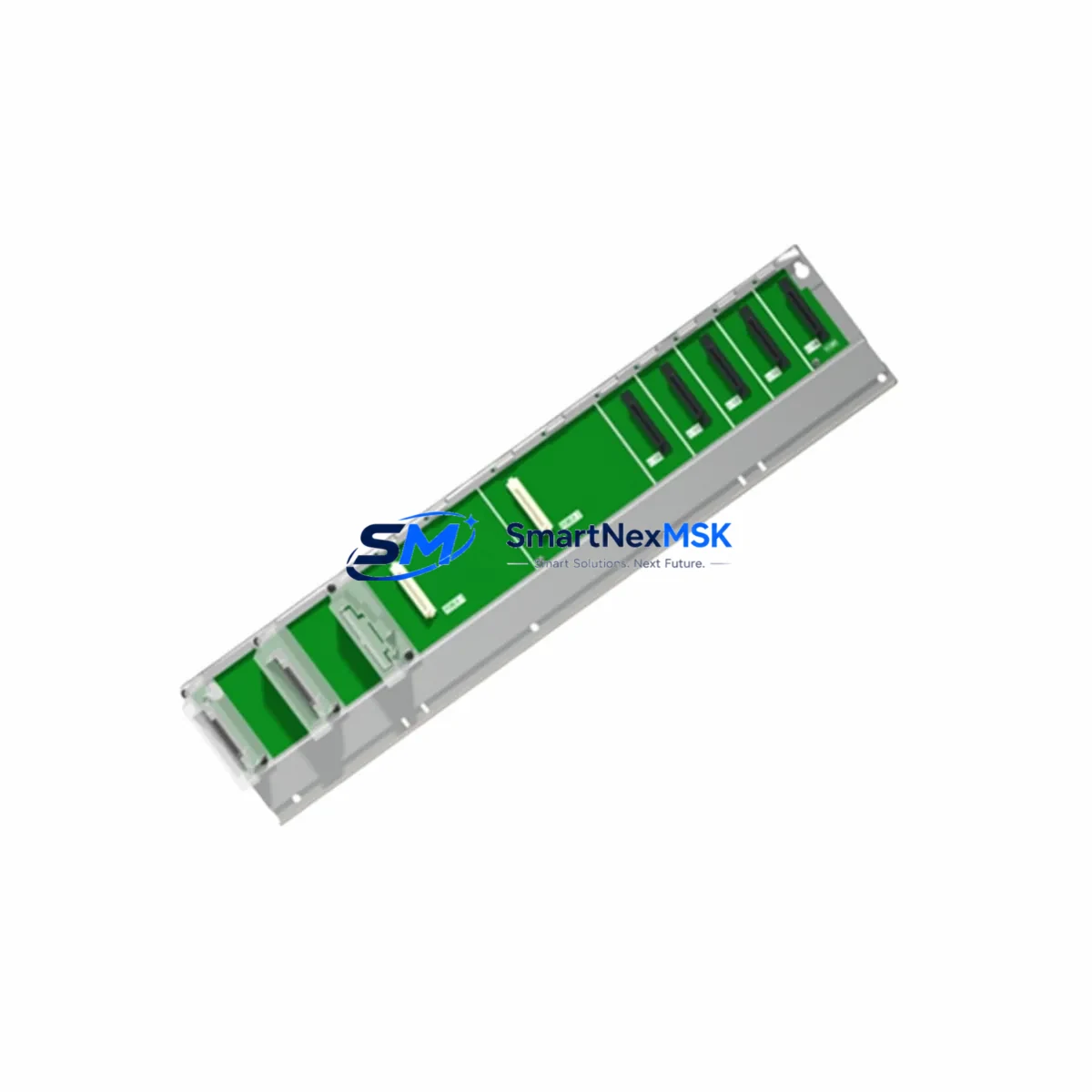
Mitsubishi Q65WRB Retrofit-Ready Base Unit for MELSEC-Q Control Systems
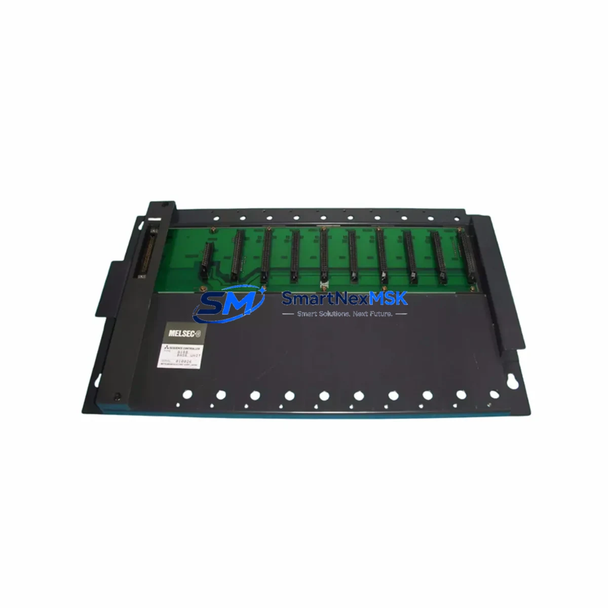
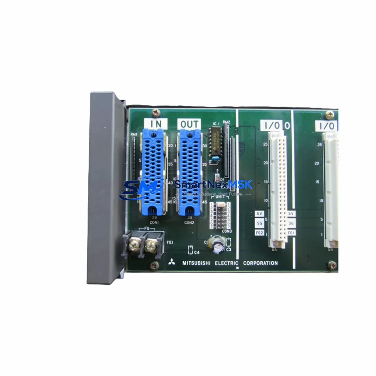
The Mitsubishi Q65WRB is a 5-slot redundant base unit designed for the MELSEC-Q series programmable logic controller platform. As legacy MELSEC-Q installations age and original spare parts become increasingly difficult to source, the Q65WRB has become a critical component in retrofit and system continuity projects across process control, power generation, water treatment, and discrete manufacturing environments. This unit provides the physical and electrical backbone for redundant CPU configurations, allowing engineers to maintain high-availability control architectures without migrating to an entirely new platform.
When planning a retrofit around the Q65WRB, the first step is verifying power budget. The redundant base unit draws power from a dedicated Q6-P4 or Q6-P4E power supply module mounted in the same rack. Engineers must confirm that the combined current draw of all installed modules — including the QJ71E71-100 Ethernet communication module, any QX40 digital input modules, QY10 digital output modules, and QJ71BR11 MELSECNET/H network modules — does not exceed the power supply’s rated output on the 5 V and 24 V rails. Overlooking this step is one of the most common causes of intermittent faults during commissioning after a rack swap.
Upgrade Compatibility Table
| Parameter | Q65WRB Specification | Retrofit Notes |
|---|---|---|
| Slot Count | 5 I/O slots | Verify module count matches existing configuration |
| Rack Type | Redundant main base | Requires paired redundant CPU (e.g. Q12PRHCPU) |
| Power Supply Slot | Dedicated PSU slot (left) | Compatible with Q6-P4 / Q6-P4E series PSU |
| Backplane Interface | MELSEC-Q bus | Not compatible with MELSEC-QnA or Q Series extension bases |
| Communication Compatibility | MELSECNET/H, CC-Link, Ethernet | Confirm network module firmware versions before swap |
| Replacement Fit | Direct drop-in for Q65WRB | No re-wiring required if terminal blocks are retained |
| Commissioning Focus | Redundancy switchover test | Verify tracking cable between redundant CPUs post-install |
| Warranty | 12 Months | Covered from date of shipment; includes DOA replacement |
Retrofit Planning for Existing Automation Systems
A successful Q65WRB retrofit begins well before the physical swap. Engineers should extract and archive the full project from the existing Q12PRHCPU or Q25PRHCPU redundant CPU using GX Works2 or GX Developer, confirming that the program version, parameter files, and device comments are all saved. If the control system includes a GOT2000 or GT16 HMI panel communicating over RS-232 or Ethernet, the HMI screen project should also be backed up and the communication settings documented before any hardware is disturbed.
Terminal wiring on the Q65WRB itself does not carry field signals — all I/O wiring connects to the individual module terminal blocks. However, the base unit’s grounding lug and power supply input terminals must be re-torqued to specification after installation. If the existing rack used a QA1S65B or similar A-series base unit in an earlier generation system, note that the Q65WRB is not mechanically or electrically interchangeable with A-series hardware; a full module set migration is required, including replacing any AJ65BT-64AD analog input modules with their Q-series equivalents such as the Q64AD.
For systems using CC-Link field networks, the QJ61BT11N CC-Link master module must be re-addressed after the rack swap if the slot position changes. Module start I/O addresses in the CPU parameters are slot-dependent on the MELSEC-Q platform, so any change in physical slot assignment requires a corresponding parameter update in GX Works2 and a full program re-download. This is a common source of post-retrofit faults that can be avoided with careful pre-migration documentation.
Downtime Control During System Migration
Minimizing production downtime during a Q65WRB swap requires a structured hot-standby transition plan. Because the Q65WRB supports redundant CPU operation, the preferred approach is to perform the base unit replacement during a planned maintenance window with the redundant system in tracking mode. The standby CPU continues to mirror the active CPU’s device memory in real time via the tracking cable connected through the QJ71TR tracking unit. Before pulling the active rack, operators should confirm that the standby CPU has achieved STANDBY status and that the system is not in a degraded single-CPU state due to a prior fault.
Once the new Q65WRB is installed and the power supply, CPU, and I/O modules are reseated, the system should be powered on in STOP mode. Engineers verify that all module LEDs indicate normal status, confirm that the CPU reads the correct I/O module configuration, and perform a redundancy switchover test before returning the line to automatic operation. The entire swap, when pre-staged with a tested spare rack, can typically be completed within a two-hour maintenance window, preserving the original ladder logic, device assignments, and HMI tag mappings without modification.
Retrofit Support FAQ
Q: Is the Q65WRB a direct replacement for my existing redundant base unit?
A: Yes, the Q65WRB is a direct drop-in replacement for units of the same model within the MELSEC-Q redundant system architecture. Physical dimensions, slot count, and backplane bus interface are identical. No re-wiring of field terminals is required, as all field connections are made at the individual I/O module level.
Q: Do I need to re-download my PLC program after replacing the base unit?
A: If the CPU modules are transferred intact from the old rack to the new Q65WRB, the program stored in the CPU’s internal flash memory is preserved. A re-download is only required if the CPU itself is also being replaced or if slot assignments for any modules have changed, which would require updated I/O parameters.
Q: How do I verify wiring and communication compatibility before installation?
A: Cross-reference the existing rack’s module list against the Q65WRB’s slot power budget. Confirm that all communication modules — including Ethernet, CC-Link, and MELSECNET/H units — are seated in the same slot positions as in the original configuration. Perform a loopback test on all network links before switching to RUN mode.
Q: What does the 12-month warranty cover?
A: All Q65WRB units ship with a 12-month warranty covering manufacturing defects and DOA (dead on arrival) failures. Units are tested prior to shipment. Warranty claims are processed with return authorization; replacement units are dispatched within 3 business days of fault confirmation.
© 2026 SMARTNEXMSK. All rights reserved.
Original Source: https://smartnexmsk.com
Contact: [email protected] | +86 18259474341