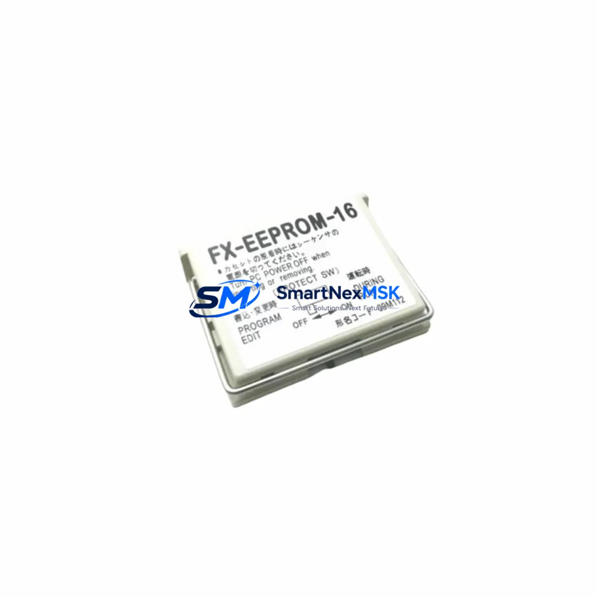
Mitsubishi FX-EEPROM-4 Retrofit-Ready Memory Cassette for MELSEC FX Series Control Systems
The Mitsubishi FX-EEPROM-4 is a 4K-step EEPROM memory cassette engineered for seamless integration into the MELSEC FX-series programmable logic controller platform. As legacy FX0, FX1, FX2, and FX2N control systems reach end-of-life support cycles, plant engineers and system integrators increasingly rely on verified replacement components like the FX-EEPROM-4 to extend operational continuity without committing to a full controller overhaul. This unit provides a direct, drop-in upgrade path that preserves existing ladder logic, retains program integrity across power cycles, and eliminates the need for battery-backed RAM in many retrofit scenarios.
For facilities running aging MELSEC FX-series panels — whether in injection molding lines, conveyor control cabinets, packaging machinery, or HVAC automation — the FX-EEPROM-4 addresses one of the most common failure points in legacy PLC systems: program memory loss due to battery depletion or RAM module degradation. Unlike volatile RAM-based storage, EEPROM retains program data without a backup power source, making it particularly valuable in environments where unplanned shutdowns are a risk.
Upgrade Compatibility Table
| Parameter | Details |
|---|---|
| Compatible Controllers | MELSEC FX0, FX0S, FX0N, FX1, FX1S, FX1N, FX2, FX2C, FX2N, FX2NC |
| Memory Capacity | 4,000 steps (4K) |
| Memory Type | EEPROM (non-volatile, no battery required) |
| Installation Interface | Direct cassette slot on FX-series main unit — no adapter required |
| Communication Compatibility | RS-232C / RS-485 via FX-232AW, FX-485AW, or FX2N-232-BD communication boards |
| Programming Tool Compatibility | GX Developer, GX Works2, FX-PCS/WIN-E via SC-09 or USB-SC09-FX programming cable |
| Replacement Recommendation | Direct replacement for original FX-EEPROM-4; also replaces FX-RAM-8 in capacity-matched applications |
| Retrofit Fit Check | Verify cassette slot orientation on FX2N-32MR, FX2N-48MR, FX2N-64MR, FX2N-128MR base units |
| Commissioning Notes | Write-protect switch must be set to OFF before program download; verify D8000 system register after transfer |
| Warranty | 12-Month Warranty — covers manufacturing defects and functional failure under normal operating conditions |
Retrofit Planning for Existing Automation Systems
When planning a retrofit around the FX-EEPROM-4, the scope of work typically extends well beyond the memory cassette itself. A complete migration assessment should account for the full control architecture of the existing panel. In most FX-series installations, the main CPU unit — such as the FX2N-32MR-001 or FX2N-64MR-ES/UL — is mounted on a DIN rail alongside a combination of digital and analog I/O expansion modules. Common expansion units in these panels include the FX2N-8EX input expansion, FX2N-8EYR relay output module, and FX2N-4AD analog input module. Each of these must be verified for address mapping continuity when the memory cassette is replaced, as incorrect module addressing can cause the CPU to fault on startup.
Power supply capacity is a critical pre-check. The FX2N series draws its 5VDC logic power from the internal power supply of the base unit, but expansion modules add to the total current draw. Before inserting the FX-EEPROM-4 and powering up, confirm that the base unit’s internal PSU — or any external FX-series power supply unit in the cabinet — has sufficient headroom. Panels that have been expanded over time may be operating near their rated current limit, and adding or swapping modules without a load audit can cause intermittent resets or program corruption.
Communication link integrity is equally important. Many legacy FX installations use the FX2N-232-BD RS-232C communication board or the FX2N-485-BD RS-485 board for SCADA connectivity, HMI communication, or inter-PLC networking. When replacing the memory cassette, the communication board remains in place, but engineers should verify that the baud rate, station number, and protocol settings stored in special data registers (D8120 for communication format, D8121 for station number) are preserved in the new program image. If the original program was backed up from a RAM cassette, these parameters must be re-entered or confirmed in the downloaded ladder program before going live.
HMI screen mapping is another area that requires attention during retrofit. Panels using a GOT1000-series or GOT2000-series HMI — connected via RS-422 or Ethernet — reference specific device addresses (M, D, Y coils and registers) that must align with the restored program. A mismatch between the HMI screen project and the PLC program version can result in incorrect status displays or failed command execution. Always verify the HMI project version against the PLC program version before commissioning.
For installations where the FX-EEPROM-4 is being used to replace a failed FX-RAM-8 or a battery-depleted memory module, the programming cable — typically a USB-SC09-FX or the older SC-09 RS-232C cable — should be on hand during the swap. After inserting the cassette, connect GX Developer or GX Works2, perform a full program write, and then execute a memory verify operation to confirm data integrity before releasing the machine to production.
Downtime Control During System Migration
Minimizing unplanned downtime during a memory cassette replacement requires a structured pre-outage preparation process. Before the maintenance window opens, the existing PLC program should be read out and saved to a PC using GX Developer or GX Works2 via the SC-09 or USB-SC09-FX cable. This backup should be stored in at least two locations — a local engineering workstation and a network share — and the file should be verified by performing a compare operation against the live PLC before the outage begins.
During the swap, the sequence is straightforward: power down the panel, remove the existing memory cassette from the CPU slot, insert the FX-EEPROM-4, power up, and immediately download the verified program. The EEPROM write cycle for a 4K-step program typically completes in under 30 seconds. Once the write is confirmed, set the write-protect switch to ON to prevent accidental overwrites, then perform a full I/O check using the monitor function in GX Developer to confirm that all input and output devices are responding correctly.
For critical production lines where even a 30-minute outage carries significant cost, consider staging a pre-programmed FX-EEPROM-4 cassette in advance. The cassette can be written offline using a spare FX-series CPU unit or a compatible programmer, then stored as a ready-to-install spare. This approach reduces the in-panel programming time to near zero and limits the maintenance window to the physical swap and I/O verification steps only. Maintaining a pre-programmed spare cassette as part of your critical spares inventory is a best practice for any facility running MELSEC FX-series equipment on continuous production schedules.
After commissioning, monitor the first production cycle closely. Check that all timers, counters, and data register values are behaving as expected, and confirm that any SCADA or HMI connected to the PLC is receiving correct status data. Document the retrofit in the panel’s maintenance log, including the cassette serial number, program version, and commissioning date.
Retrofit Support FAQ
Q: Is the FX-EEPROM-4 a direct replacement for the FX-RAM-8?
A: The FX-EEPROM-4 (4K steps) and FX-RAM-8 (8K steps) differ in capacity. If your existing program is 4,000 steps or fewer, the FX-EEPROM-4 is a functional replacement. For programs exceeding 4K steps, consider the FX-EEPROM-8 instead. Always verify program step count in GX Developer before ordering.
Q: Do I need to reconfigure communication settings after installing the FX-EEPROM-4?
A: Communication parameters such as baud rate, station number, and protocol format are stored in special data registers within the PLC program, not in the memory cassette hardware. As long as your restored program includes the correct D8120 and D8121 register values, communication with connected HMIs or SCADA systems will resume normally after the swap.
Q: What pre-shipment testing is performed on the FX-EEPROM-4?
A: Each unit undergoes functional verification prior to dispatch, including cassette interface continuity checks and EEPROM read/write cycle testing. Units are shipped with a 12-month warranty covering manufacturing defects and functional failure under normal operating conditions. Warranty claims are supported with replacement dispatch within standard lead times.
Q: Can the FX-EEPROM-4 be used in an FX0N or FX1S controller?
A: Yes. The FX-EEPROM-4 is compatible with the FX0N and FX1S series, subject to the program step limit of the target CPU. The FX1S supports up to 2,000 steps, so the cassette will operate within that constraint. For FX0N applications, confirm the cassette slot type on your specific base unit model before installation.
© 2026 SMARTNEXMSK. All rights reserved.
Original Source: https://smartnexmsk.com
Contact: [email protected] | +86 18259474341