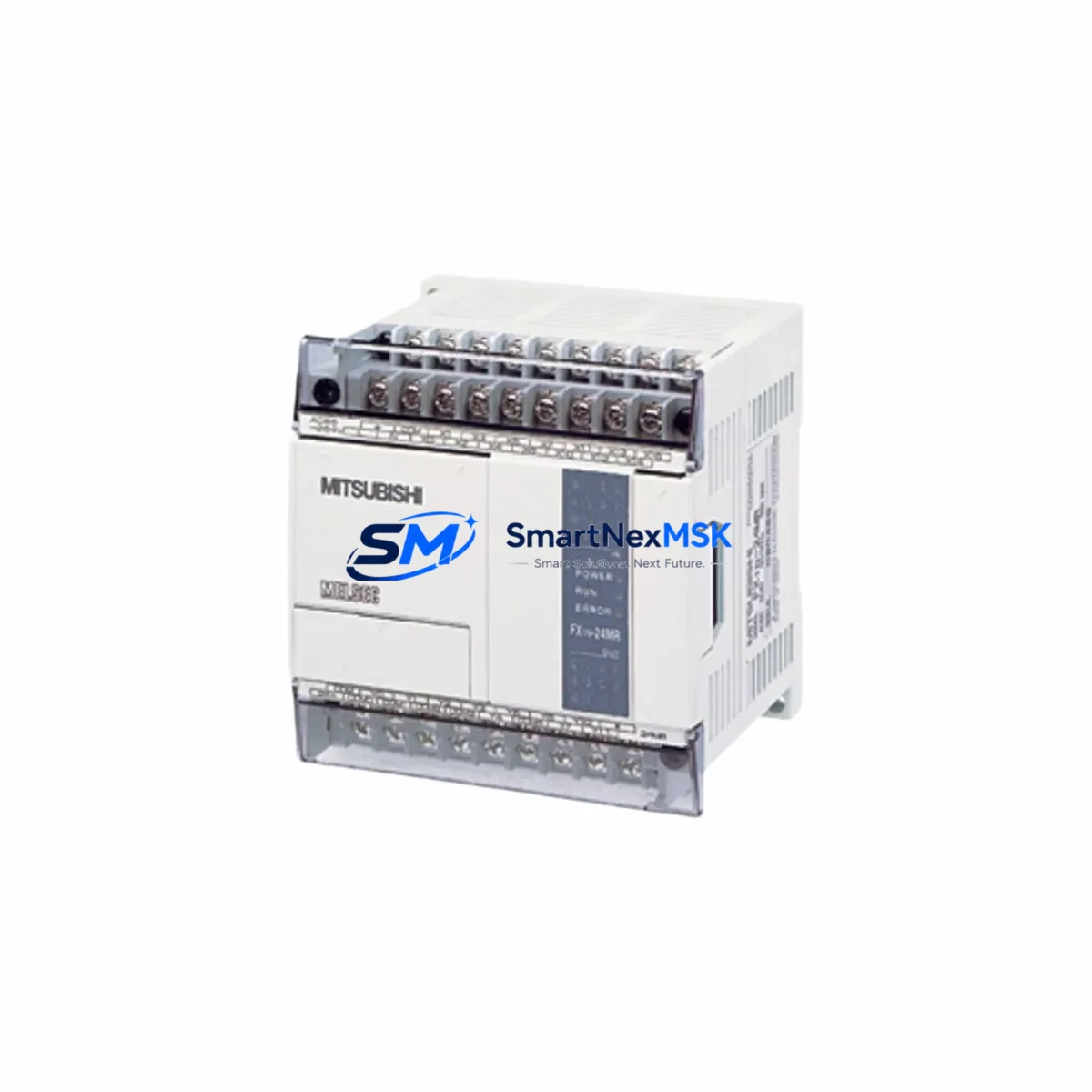
Mitsubishi FX1N-24MT-001 Retrofit-Ready Transistor PLC for MELSEC FX1N Control Systems
The Mitsubishi FX1N-24MT-001 is a compact, high-performance programmable logic controller designed for seamless integration into existing MELSEC FX1N-series automation architectures. As legacy FX1N systems approach end-of-life and original spare parts become increasingly scarce, the FX1N-24MT-001 serves as the definitive retrofit-ready replacement — offering full program compatibility, identical terminal layout, and transistor (NPN sink) output configuration that matches the original control cabinet wiring without modification.
With 14 DC input points and 10 transistor output points in a compact DIN-rail-mountable housing, this unit supports direct substitution in production lines, packaging machinery, conveyor systems, and process control panels where the original FX1N-24MT or FX1N-24MT-D has been discontinued or is no longer available through standard distribution channels. The onboard RS-422 programming port maintains full compatibility with GX Developer and GX Works2 software, allowing engineers to upload existing ladder logic programs without rewriting a single rung.
Upgrade Compatibility Table
| Parameter | FX1N-24MT-001 (This Unit) | Original FX1N-24MT / FX1N-24MT-D |
|---|---|---|
| I/O Configuration | 14 DI / 10 DO (Transistor NPN) | 14 DI / 10 DO (Transistor NPN) |
| Power Supply | 100–240 VAC, 50/60 Hz | 100–240 VAC, 50/60 Hz |
| Programming Port | RS-422 (Mini DIN 8-pin) | RS-422 (Mini DIN 8-pin) |
| Communication Compatibility | FX1N, FX2N, FX3U protocol compatible | FX1N native |
| Software Compatibility | GX Developer / GX Works2 | GX Developer |
| Expansion Module Support | FX1N-8EX, FX1N-8EYT, FX2N-16EX | FX1N expansion series |
| Installation | DIN rail or panel mount | DIN rail or panel mount |
| Retrofit Recommendation | Direct drop-in replacement | — |
| Debugging Notes | Verify D-register values post-upload | — |
| Warranty | 12 Months | OEM — varies |
Retrofit Planning for Existing Automation Systems
Successful retrofit of an FX1N-24MT-001 into a legacy control cabinet begins with a thorough audit of the existing system architecture. Engineers should document the current terminal block wiring — particularly the 24 VDC common lines shared between input modules such as the FX1N-8EX and the main CPU — before powering down the panel. The FX1N-24MT-001 uses the same screw-terminal pitch as the original unit, so existing wire ferrules and cable labels can be reused directly, significantly reducing rewiring time.
For systems that include analog expansion modules such as the FX1N-2AD-BD or FX1N-1DA-BD, verify that the BD connector slot on the replacement unit is unoccupied and that the analog scaling parameters stored in D-registers are backed up prior to program transfer. If the original system communicates with an HMI panel — such as a Mitsubishi GOT1000 or GOT2000 series display — confirm that the RS-422 communication parameters (baud rate, station number, data format) in the HMI project match those configured in the PLC program. No hardware changes to the communication cable or terminal resistor are required when replacing like-for-like within the FX1N platform.
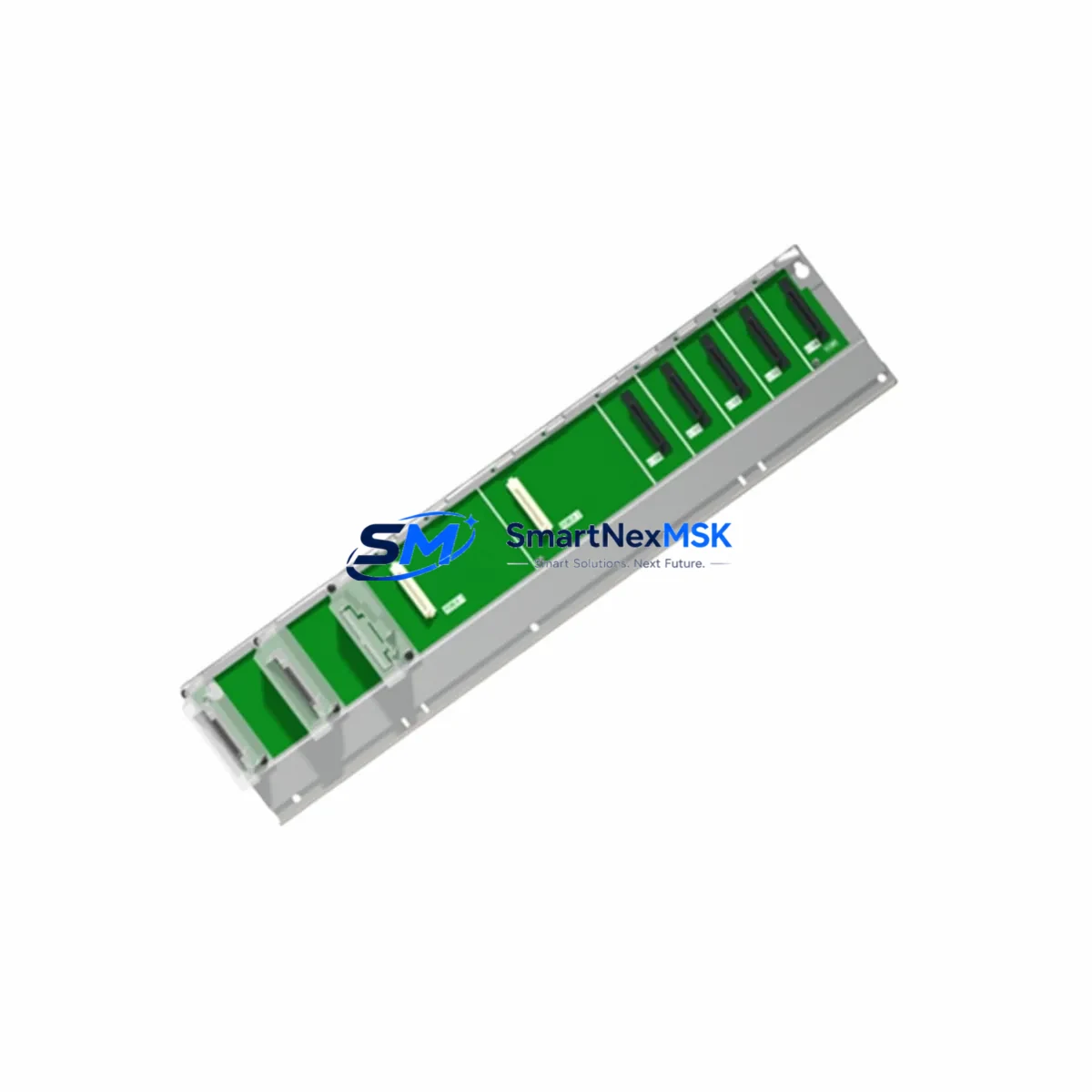
Where the retrofit involves migrating from an older FX0N or FX1S controller to the FX1N-24MT-001, engineers must account for differences in instruction set coverage and memory capacity. The FX1N supports up to 8,000 steps of program memory, compared to 2,000 steps on the FX1S, providing headroom for expanded logic without requiring a larger chassis. Expansion I/O such as the FX1N-8EYT transistor output module or the FX1N-16EX input expansion can be added to the right side of the base unit using the standard FX1N expansion bus connector, eliminating the need for a separate rack or backplane.
For installations that require RS-485 multi-drop communication — common in SCADA-connected production lines — the FX1N-485-BD communication board can be installed in the BD slot to enable Modbus RTU or Mitsubishi FX protocol over a two-wire RS-485 network. This allows the FX1N-24MT-001 to integrate directly into existing fieldbus topologies without replacing the communication infrastructure. Power supply capacity should be verified: the FX1N-24MT-001 draws a maximum of 30 VA from the AC supply, and the total expansion current budget (5 VDC internal bus) must be calculated to ensure that all attached expansion modules — including the FX1N-CNV-BD converter board if used — remain within the 300 mA expansion bus limit.
Downtime Control During System Migration
Minimizing production downtime during a PLC swap requires a structured pre-migration checklist. Before the maintenance window opens, the existing program should be read out from the original FX1N CPU using GX Developer or GX Works2 and saved in both .gxw project format and a plain-text instruction list export. All current D-register values, timer presets, and counter settings should be documented using the device batch monitor function, as these values are not always preserved in the program file alone.
During the physical swap, label all terminal connections before disconnecting any wiring. The FX1N-24MT-001 can be mounted and wired while the original unit is still in place if panel space permits, allowing a parallel pre-check before the final cutover. Once the replacement unit is installed and wired, write the saved program to the new CPU, restore D-register values manually or via a CSV device import, and perform a dry-run in STOP mode to verify output coil states before switching to RUN. If the system includes a GOT series HMI, confirm that the HMI communication link is re-established and that all screen tags are reading correctly before releasing the line back to production. Total cutover time for a well-prepared FX1N-24MT-001 replacement is typically under 45 minutes.
Retrofit Support FAQ
Q1: Is the FX1N-24MT-001 a direct replacement for the FX1N-24MT and FX1N-24MT-D?
Yes. The FX1N-24MT-001 shares the same I/O count, terminal layout, power supply specification, and transistor output type as both the FX1N-24MT and FX1N-24MT-D. Existing programs written for either model can be uploaded without modification. Verify that any model-specific comments in the GX Developer project are updated to reflect the new unit designation.
Q2: Can I connect my existing FX1N expansion modules without rewiring?
Yes. The FX1N-24MT-001 supports the full range of FX1N-series expansion modules — including the FX1N-8EX, FX1N-8EYT, FX1N-2AD-BD, and FX1N-1DA-BD — via the standard right-side expansion connector. No additional adapter or converter is required. Confirm total expansion bus current draw does not exceed 300 mA before adding modules.
Q3: What commissioning steps are required after installation?
After writing the program and restoring device values, perform the following: (1) verify all input signals in the device monitor with the machine in a safe state; (2) check output coil states in STOP mode against the original I/O map; (3) confirm HMI communication link if a GOT panel is connected; (4) run one full machine cycle in manual mode before enabling automatic operation. Document the commissioning results for your maintenance records.
Q4: What does the 12-month warranty cover?
All FX1N-24MT-001 units supplied by SMARTNEXMSK carry a 12-month warranty covering manufacturing defects and functional failures under normal operating conditions. Each unit undergoes pre-shipment functional testing including I/O verification, program write/read cycle, and power supply load test. Warranty claims are supported by our technical team with replacement dispatch within 5 business days upon defect confirmation.
© 2026 SMARTNEXMSK. All rights reserved.
Original Source: https://smartnexmsk.com
Contact: [email protected] | +86 18259474341