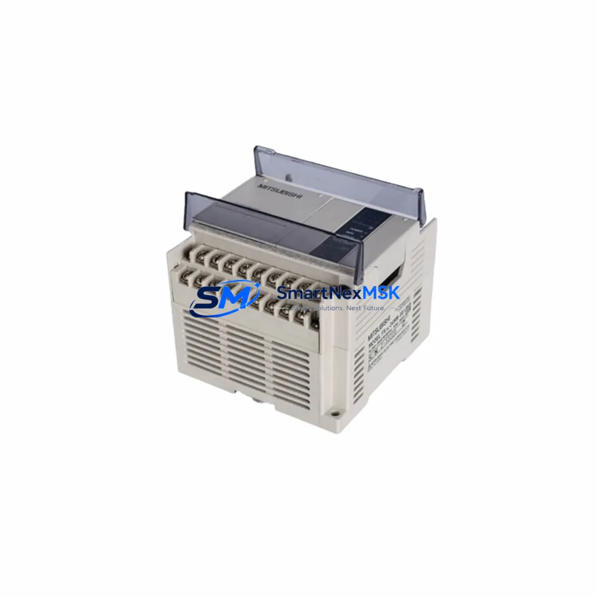
Mitsubishi FX1N-40MR-001 Retrofit-Ready Relay PLC: Compatible Modernization for FX1N Control Systems
The Mitsubishi FX1N-40MR-001 is a compact, high-reliability programmable logic controller from Mitsubishi Electric’s FX1N Series, featuring 24 DC inputs and 16 relay outputs in a single base unit. As legacy FX1N systems age and original spare parts become increasingly difficult to source, the FX1N-40MR-001 remains one of the most sought-after retrofit and replacement modules for small-to-medium automation lines across manufacturing, packaging, material handling, and building automation sectors.
This unit is fully compatible with the FX1N Series programming environment and can be configured using GX Developer or GX Works2 software via the RS-422 programming port. Whether you are replacing a failed controller on an existing production line, upgrading from an older FX0N-40MR or FX2N-40MR platform, or consolidating a multi-rack legacy system into a single compact controller, the FX1N-40MR-001 provides a reliable, cost-effective path forward without requiring a full system redesign.
Upgrade Compatibility Table
| Parameter | FX1N-40MR-001 (This Unit) | Retrofit Notes |
|---|---|---|
| I/O Configuration | 24 DC Inputs / 16 Relay Outputs | Verify field wiring matches relay output type; transistor output variants (FX1N-40MT) are not pin-compatible |
| Power Supply | 100–240 VAC, 50/60 Hz | Confirm panel supply voltage before installation; DC-powered variants require separate power module |
| Programming Interface | RS-422 (Mini-DIN 8-pin) | Use SC-09 or USB-SC09-FX programming cable; confirm cable compatibility with laptop COM port or USB adapter |
| Communication Expansion | FX1N-232-BD / FX1N-485-BD / FX1N-CNV-BD | Existing communication boards from original unit are typically reusable; verify firmware revision |
| Expansion Modules | FX2N-series I/O expansion via FX1N-CNV-BD | Up to 128 I/O points total with expansion; confirm backplane connector alignment |
| DIN Rail Mounting | Standard 35mm DIN rail | Footprint matches FX1N-40MR-ES/UL; no panel modification required in most cases |
| Program Memory | 8,000 steps | Verify existing program does not exceed step limit; use GX Developer to check step count before transfer |
| Replacement Compatibility | FX0N-40MR, FX1N-40MR-ES/UL, FX2N-40MR (with wiring review) | Terminal layout differences exist between FX0N and FX1N; refer to wiring diagram before reconnecting field cables |
| Warranty | 12-Month Warranty — covers manufacturing defects; includes pre-shipment functional test | |
Retrofit Planning for Existing Automation Systems
Successful retrofit of an FX1N-40MR-001 into an existing control cabinet begins well before the physical swap. Engineers should start by auditing the current panel layout, documenting all terminal block wiring, and photographing the existing FX1N or FX0N unit’s I/O connections before disconnection. In many legacy installations, the FX1N-40MR-001 shares the same DIN rail footprint and terminal strip layout as the FX1N-40MR-ES/UL, making direct replacement straightforward.
Where the original system uses FX2N-16EX or FX2N-16EYR expansion modules connected via the right-side expansion bus, these modules can typically be retained and reconnected to the replacement FX1N-40MR-001 using the existing flat ribbon connector. However, if the legacy system includes an FX2N-32CCL CC-Link communication module or an FX2N-16CCL-M master module, engineers must verify that the FX1N Series supports the same CC-Link station configuration, as FX1N has more limited CC-Link support compared to FX2N.
For systems that rely on RS-485 Modbus RTU communication — common in SCADA-connected lines — the FX1N-485-BD communication board can be installed in the option board slot of the FX1N-40MR-001 to restore serial communication links. If the original system used an FX1N-232-BD for RS-232 HMI connections to a GOT1000 or GOT2000 series HMI panel, the same board is compatible with the replacement unit, and the HMI screen project typically requires no modification provided the PLC device addresses remain unchanged.
Power supply capacity is a critical checkpoint. The FX1N-40MR-001’s internal 24 VDC service power output is rated at 250 mA, sufficient for a limited number of proximity sensors or input devices. If the existing panel draws more than this from the PLC’s service supply, a dedicated external 24 VDC power supply — such as a Mitsubishi PS-5VDC or a third-party DIN rail PSU — should be verified as part of the retrofit plan. Overloading the internal service supply is a common cause of intermittent input faults after replacement.
Module addressing and program compatibility should be confirmed using GX Developer or GX Works2 before the cutover. Upload the existing program from the original PLC if it is still operational, verify the step count is within the 8,000-step limit of the FX1N-40MR-001, and check that all special function registers (D8000–D8255) used in the program are supported by the FX1N instruction set. If the legacy system used an FX2N-4AD analog input module or FX2N-2DA analog output module, confirm that the FROM/TO instructions in the program reference the correct buffer memory addresses for the FX1N expansion bus.
Downtime Control During System Migration
Minimizing unplanned downtime during an FX1N-40MR-001 replacement requires a structured cutover plan. The recommended approach is to prepare the replacement unit off-line: load the verified program, configure communication parameters, and perform a bench test with simulated I/O signals before the scheduled maintenance window. This pre-commissioning step alone can reduce on-site cutover time from several hours to under 30 minutes in most cases.
During the physical swap, label all field wiring before disconnection using numbered cable markers corresponding to the terminal diagram. The FX1N-40MR-001’s terminal strip layout is consistent with the FX1N-40MR-ES/UL, so if the original unit was an FX1N variant, reconnection can proceed terminal-by-terminal without referencing the full wiring schematic. For systems migrating from an FX0N-40MR, the terminal numbering differs and the wiring diagram must be consulted to avoid miswiring output relays.
After reconnection, power up the system with outputs disabled (using the RUN/STOP switch or a program-level output inhibit) and verify all input signals are reading correctly on the GX Developer monitor before enabling outputs. This staged power-up sequence protects actuators and field devices from unexpected activation during the first scan cycle. Once inputs are confirmed, enable outputs and monitor the first 10–15 machine cycles before returning the line to full production. All units supplied by SMARTNEXMSK are pre-tested for I/O continuity and program execution prior to shipment, reducing the risk of receiving a defective unit and further protecting your maintenance schedule.
Retrofit Support FAQ
Q1: Is the FX1N-40MR-001 a direct drop-in replacement for the FX1N-40MR-ES/UL?
Yes. The FX1N-40MR-001 and FX1N-40MR-ES/UL share the same hardware architecture, I/O count, terminal layout, and programming environment. The primary difference is the power supply input specification and regional certification markings. In most panel installations, the replacement is direct with no wiring or program changes required.
Q2: Can I reuse my existing SC-09 programming cable and GX Developer project files?
Yes. The FX1N-40MR-001 uses the same RS-422 Mini-DIN 8-pin programming port as all FX1N Series units. Existing SC-09 or USB-SC09-FX cables are fully compatible. GX Developer project files (.gxw) and GX Works2 Simple Project files created for FX1N targets can be written directly to the replacement unit without modification, provided the program step count does not exceed 8,000 steps.
Q3: What should I check regarding output wiring when replacing from an FX0N-40MR?
The FX0N-40MR and FX1N-40MR-001 have different terminal strip layouts. Output common terminal groupings and numbering differ between the two series. Before reconnecting field cables, compare the FX0N and FX1N terminal diagrams side by side and re-map each output wire to its correct FX1N terminal. Failure to do so can result in miswired relay outputs and potential damage to connected actuators on first power-up.
Q4: What does the 12-month warranty cover, and is pre-shipment testing performed?
All FX1N-40MR-001 units supplied by SMARTNEXMSK carry a 12-month warranty covering manufacturing defects and functional failures under normal operating conditions. Each unit undergoes a pre-shipment functional test verifying I/O operation, power supply output, and communication port integrity before dispatch. In the event of a warranty claim, SMARTNEXMSK provides replacement or repair support with documented test records available upon request.
© 2026 SMARTNEXMSK. All rights reserved.
Original Source: https://smartnexmsk.com
Contact: [email protected] | +86 18259474341