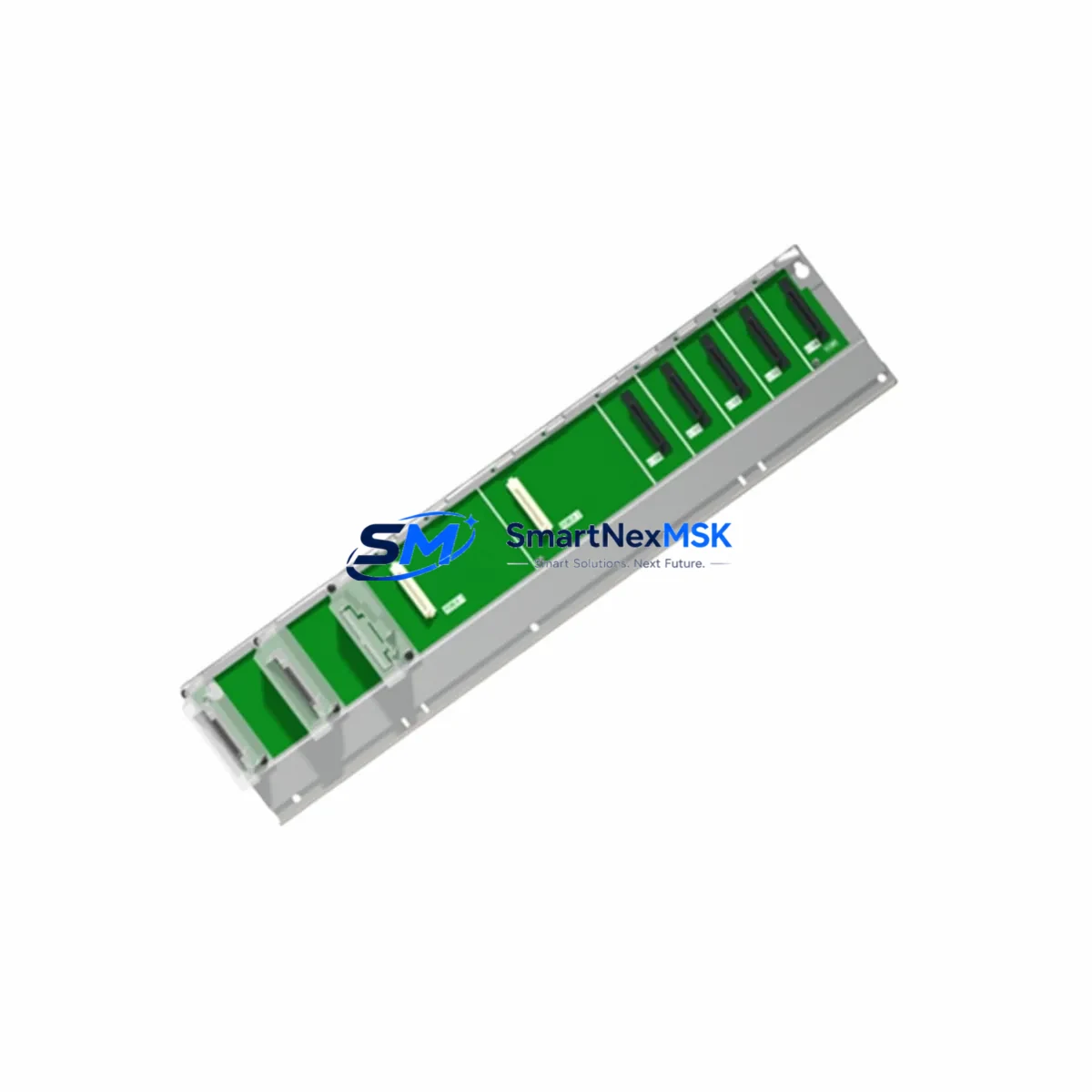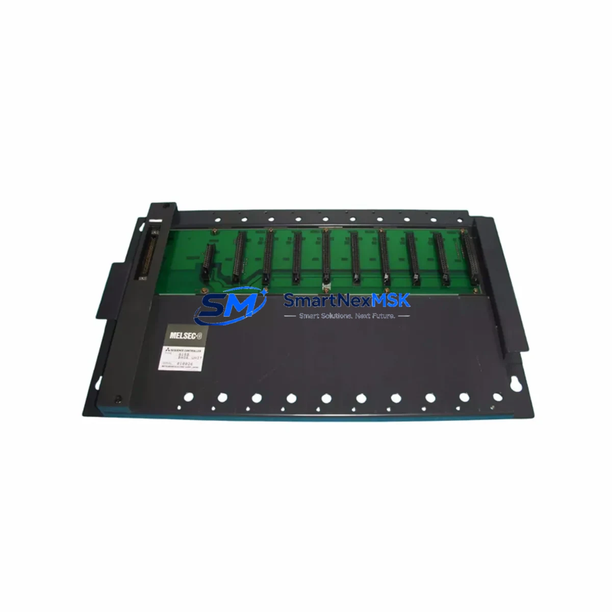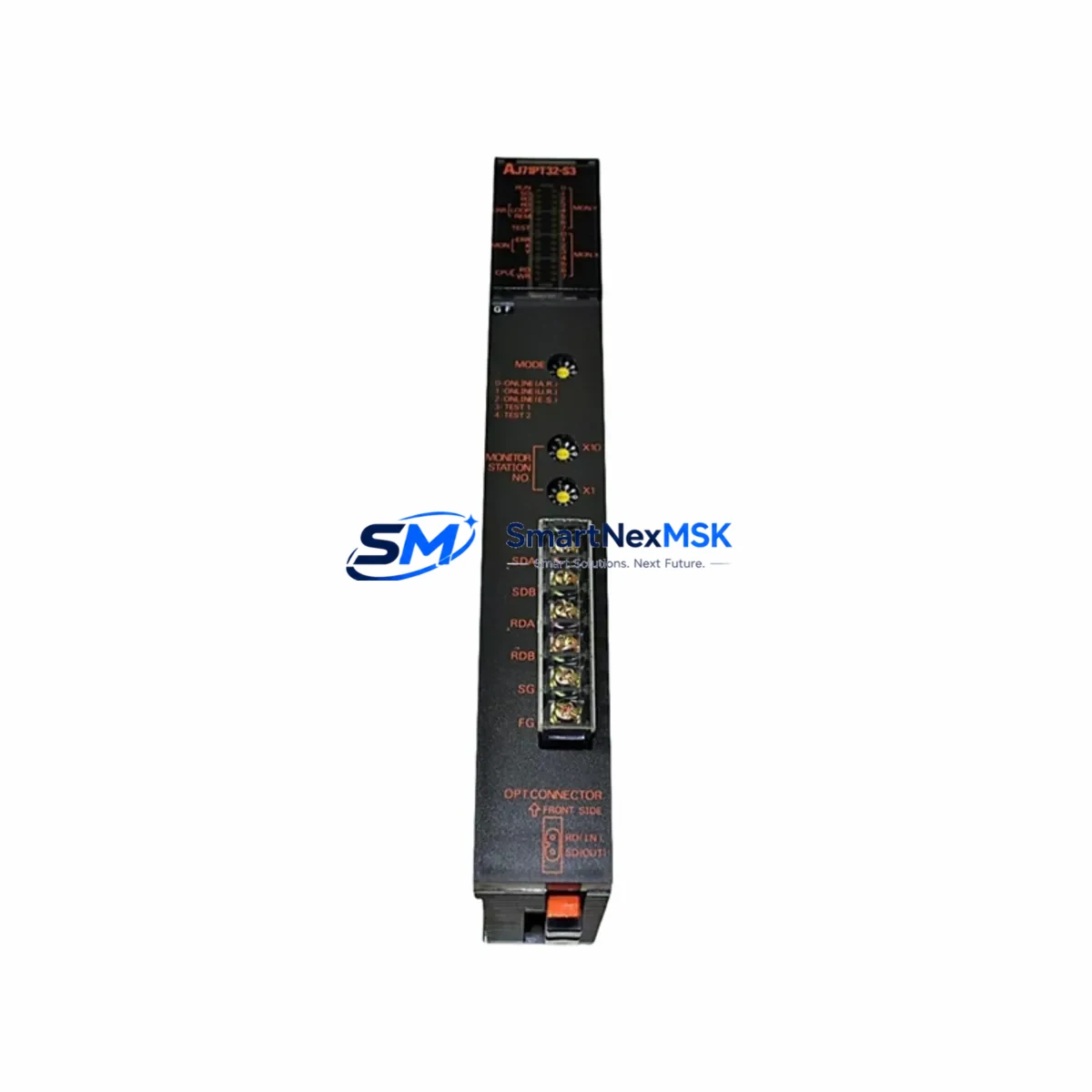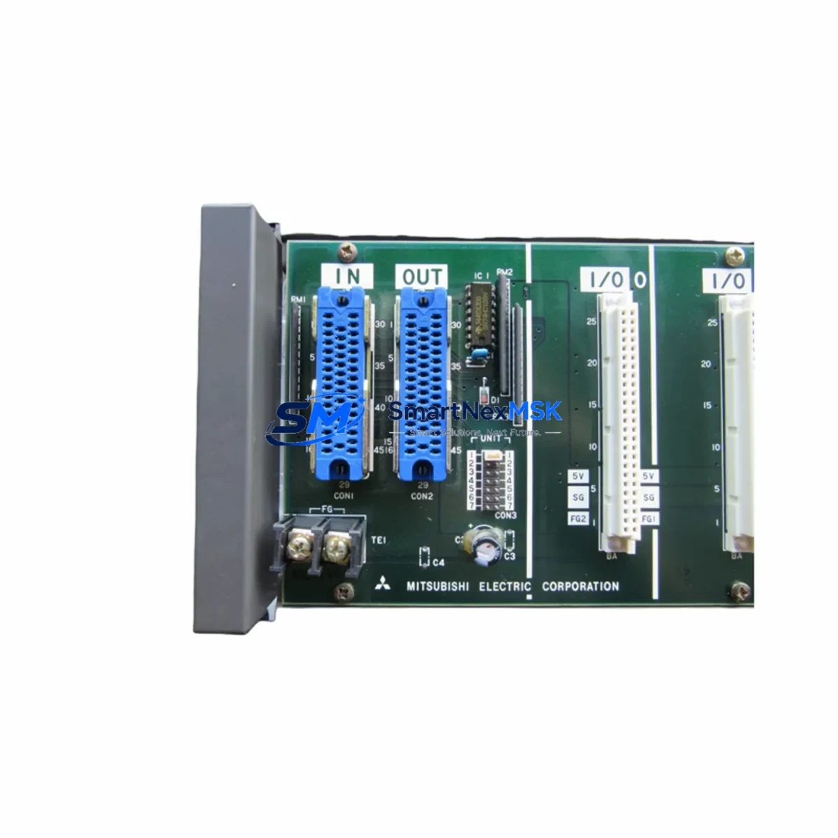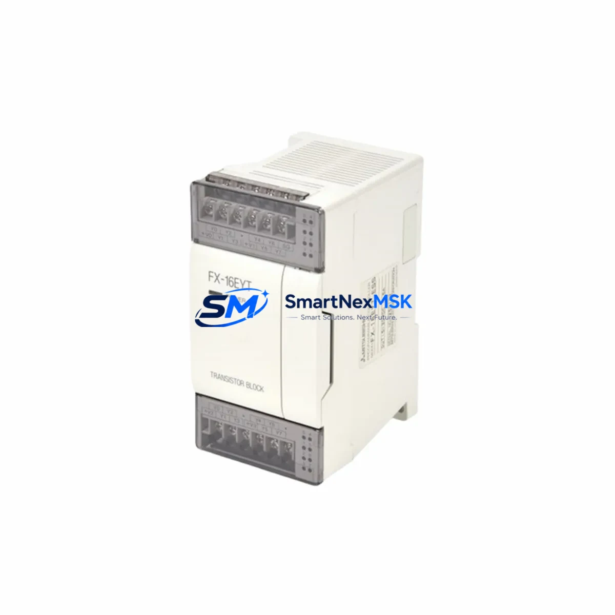
Mitsubishi FX2-40AW Retrofit-Ready Link Module for MELSEC FX2 Control Systems
The Mitsubishi FX2-40AW is a retrofit-ready link module engineered for seamless integration into legacy MELSEC FX2 Series programmable logic controller systems. As production lines built around the FX2 platform age and original spare parts become increasingly scarce, the FX2-40AW provides a verified, drop-in compatible replacement path that preserves existing wiring infrastructure, retains Melsec communication protocol compatibility, and eliminates the need for full system redesign. Whether you are managing a planned upgrade cycle or responding to an unplanned component failure, the FX2-40AW is stocked and ready to ship from Xiamen with a 12-month warranty.
Upgrade Compatibility Table
| Parameter | Detail |
|---|---|
| Replaced / Superseded Model | Mitsubishi FX2-40AW (original OEM) |
| Compatible Series | MELSEC FX2, FX2C, FX2N (link expansion slot) |
| Communication Protocol | Melsec-I/O Link, RS-422 compatible |
| Backplane / Rack Interface | Direct FX2 expansion connector — no adapter required |
| Terminal Wiring | Identical terminal layout to original FX2-40AW; existing field wiring reusable |
| Module Address Setting | DIP switch configurable; matches original address map |
| Power Consumption | Verify FX2 power supply (e.g. FX2-32ET or FX2-48MR base unit) total load budget before installation |
| Program Compatibility | Existing GX Developer / GX Works2 ladder logic retained without modification |
| HMI Screen Compatibility | GOT1000 / GOT2000 series HMI screens remain valid; no tag remapping required |
| Commissioning Requirement | Power-cycle PLC after module seating; verify link LED status and I/O map in GX Works2 |
| Warranty | 12 months from date of shipment; outgoing test report included |
| Origin | Japan |
Retrofit Planning for Existing Automation Systems
Successful FX2-40AW replacement begins well before the module arrives on site. Engineers responsible for legacy MELSEC FX2 control cabinets should audit the full rack configuration, starting with the FX2-48MR or FX2-32ET base unit to confirm available expansion slots and total power budget. The FX2 power supply rail is shared across all expansion modules, so adding or replacing a link module requires verifying that the combined current draw of all installed units — including any FX2-8EX digital input expansion modules or FX2-8EYR relay output modules — does not exceed the base unit’s rated output.
Terminal block wiring on the FX2-40AW follows the original Mitsubishi terminal layout, meaning field cables terminated to the legacy module can be transferred directly to the replacement unit without re-labelling or re-routing. This is a critical time-saver during emergency replacements where production downtime must be minimized. Before disconnecting the original module, photograph or document the terminal assignments and cross-reference against the existing panel wiring diagram.
For systems that also incorporate FX2N-16CCL-M CC-Link master modules or FX2N-32CCL CC-Link interface modules on the same rack, confirm that the link module address configured on the FX2-40AW DIP switches does not conflict with existing station assignments. Address conflicts are a common source of communication faults after module swap and are easily avoided with a pre-installation station map review.
Where the control system includes a GOT1000 GT1155 or GOT2000 GT2107 HMI panel communicating via RS-422 to the FX2 CPU, no screen project changes are required after the FX2-40AW replacement, provided the CPU unit — typically an FX2N-48MR-001 or FX2N-64MR — remains in service. The HMI tag database references the CPU’s device memory, not the link module directly, so communication continuity is maintained automatically once the replacement module is powered and the link LED confirms active status.
For sites planning a broader migration from FX2 to FX5U architecture, the FX2-40AW serves as a stable interim solution that keeps the existing line running while the new MELSEC iQ-F FX5U-80MT/ESS control platform is configured, programmed, and validated offline. This staged approach — replace the failed link module now, migrate the full system during the next planned shutdown — is the most cost-effective strategy for minimizing both immediate downtime and long-term obsolescence risk.
Programming cable access during commissioning typically requires an FX-USB-AW or SC-09 programming cable connected to the FX2 CPU’s RS-422 port. Ensure GX Developer version 8.86S or later is available on the commissioning laptop to support FX2 series parameter read/write operations.
Downtime Control During System Migration
Unplanned downtime caused by a failed FX2-40AW link module can be contained to under two hours when the replacement unit is pre-staged and the commissioning procedure is prepared in advance. The recommended sequence is: (1) back up the current PLC program from the FX2 CPU using GX Developer before any hardware change; (2) power down the control cabinet and discharge the bus; (3) remove the failed FX2-40AW by releasing the DIN rail clip and disconnecting the expansion connector; (4) seat the replacement module, confirm the DIP switch address matches the original setting, and reconnect field terminals using the documented wiring reference; (5) restore power and observe the LINK LED — a steady green indicates successful link establishment; (6) perform a forced I/O test from GX Works2 to verify all mapped points respond correctly before releasing the line to production.
For systems where the FX2 CPU holds the only copy of the active program, the pre-replacement backup step is non-negotiable. A corrupted or missing program after a hardware swap is the single largest source of extended downtime in legacy PLC maintenance. Storing a verified program backup on a dedicated USB drive kept inside the control cabinet door is a best practice that eliminates this risk entirely.
Where the production process cannot tolerate even a brief interruption, consider pre-configuring the replacement FX2-40AW with the correct DIP switch address and performing a hot-swap during a micro-stop window. While the FX2 platform does not support true hot-swap at the hardware level, a coordinated power-cycle lasting less than 30 seconds is sufficient for module recognition and link re-establishment in most FX2 configurations.
Retrofit Support FAQ
Q1: Is the FX2-40AW a direct drop-in replacement for the original Mitsubishi FX2-40AW?
Yes. The FX2-40AW supplied by SMARTNEXMSK is dimensionally and electrically compatible with the original Mitsubishi Electric FX2-40AW. The expansion connector, terminal layout, DIP switch address range, and Melsec-I/O Link protocol implementation are identical to the OEM specification. No wiring modifications or program changes are required for a like-for-like replacement.
Q2: What commissioning steps are required after installation?
After seating the module and reconnecting field terminals, power-cycle the FX2 base unit. Observe the LINK LED on the FX2-40AW front panel — steady green confirms successful link establishment. Open GX Works2 or GX Developer, connect to the FX2 CPU via the FX-USB-AW programming cable, and perform a forced I/O test to verify all mapped input and output points respond as expected. No parameter file changes are required if the DIP switch address matches the original module setting.
Q3: Can this module be used in an FX2N rack alongside FX2N-series I/O expansion modules?
The FX2-40AW is designed for the FX2 expansion bus. While the FX2N series shares physical rack dimensions with FX2, the expansion bus protocol differs. Use in an FX2N rack requires verification of bus compatibility. For FX2N-native link requirements, the FX2N-16CCL-M CC-Link master or FX2N-32CCL interface module is the recommended solution. Contact our technical team with your rack configuration for a compatibility confirmation before ordering.
Q4: What does the 12-month warranty cover, and is an outgoing test report included?
Every FX2-40AW unit shipped by SMARTNEXMSK is bench-tested prior to dispatch. A test report confirming power-on, link establishment, and I/O mapping verification is included with each shipment. The 12-month warranty covers manufacturing defects and functional failures under normal operating conditions. Units that fail within the warranty period are replaced or refunded at no additional cost. Warranty claims are processed within 5 business days of fault confirmation.
© 2026 SMARTNEXMSK. All rights reserved.
Original Source: https://smartnexmsk.com
Contact: [email protected] | +86 18259474341