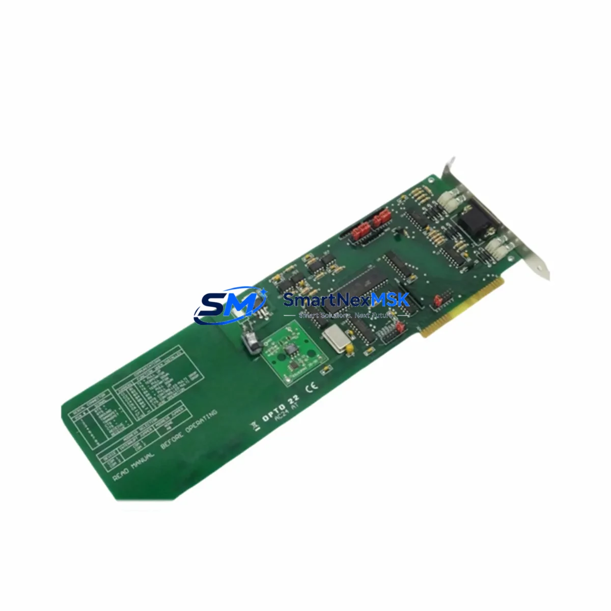
OPTO 22 SNAP-AIV Retrofit-Ready Analog Input Module for SNAP I/O Control Systems
The OPTO 22 SNAP-AIV is a high-precision analog input voltage module engineered for the SNAP I/O distributed I/O platform. Designed to accept ±10 VDC analog signals, this module delivers reliable signal acquisition in demanding industrial environments — making it a preferred choice for engineers managing legacy system upgrades, discontinued spare part replacements, and control cabinet modernization projects. Whether you are migrating from an aging SNAP-B series brain or expanding an existing SNAP-PAC-R1 rack-based architecture, the SNAP-AIV provides a verified drop-in retrofit path with minimal re-engineering.
For facilities running older SNAP I/O configurations built around the SNAP-B3000-ENET or SNAP-ENET-D64 network brains, the SNAP-AIV integrates directly onto standard SNAP mounting racks without requiring backplane modifications. Its 4-channel analog input design is fully compatible with the SNAP rack system, including the SNAP-HD-16 and SNAP-HD-8 mounting racks, allowing engineers to slot in replacement modules during scheduled maintenance windows without disturbing adjacent I/O channels or rewiring terminal blocks.
When planning a retrofit, engineers must verify several critical parameters before commissioning the SNAP-AIV into an existing control loop. Power supply capacity should be confirmed against the SNAP power supply module — typically the SNAP-PS5 or SNAP-PS24 — to ensure the rack’s total current draw remains within rated limits after adding or replacing modules. Terminal wiring must be inspected for correct polarity and shielding, particularly in high-noise environments where variable frequency drives or servo amplifiers operate in proximity to signal wiring. The SNAP-AIV’s screw-terminal interface is compatible with standard 14–22 AWG field wiring, simplifying direct reconnection from decommissioned modules.
Upgrade Compatibility Table
| Parameter | SNAP-AIV Specification | Retrofit Notes |
|---|---|---|
| Signal Type | ±10 VDC Analog Voltage Input | Verify field sensor output range matches ±10 V |
| Channels | 4 Channels per Module | Map channel addresses in PAC Control or OptoScript |
| Rack Compatibility | SNAP HD-4, HD-8, HD-16 Racks | No backplane modification required |
| Brain / Controller Compatibility | SNAP-PAC-R1, SNAP-PAC-R2, SNAP-B3000-ENET | Confirm firmware version supports analog I/O map |
| Communication Protocol | OPTO 22 SNAP I/O Bus (proprietary) | No protocol migration required within SNAP platform |
| Power Requirement | Powered via SNAP rack bus | Verify SNAP-PS5 / SNAP-PS24 capacity before adding modules |
| Terminal Interface | Screw Terminal, 14–22 AWG | Direct reconnection from legacy module wiring |
| Module Address | Assigned by slot position on rack | Update PAC Control strategy I/O table after slot change |
| HMI Compatibility | Compatible with SNAP-PAC-S1 and Ethernet-based HMI | Update HMI tag bindings if slot address changes |
| Warranty | 12-Month Warranty | Covered from date of shipment; includes functional test |
Retrofit Planning for Existing Automation Systems
A successful SNAP-AIV retrofit begins with a thorough audit of the existing control architecture. In most legacy SNAP I/O installations, the analog input channels are mapped within a PAC Control strategy file, where each module’s slot position on the rack corresponds to a defined I/O point address. Before physically replacing a failed or discontinued analog input module, engineers should export the current strategy from the SNAP-PAC-R1 or SNAP-PAC-R2 controller and document all existing I/O point names, engineering unit scaling, and alarm setpoints associated with the affected channels.
In installations where the SNAP I/O rack is paired with a SNAP-ENET-D64 digital brain or a legacy SNAP-B3000-ENET Ethernet brain, the SNAP-AIV can be installed in any available analog-capable slot without requiring a firmware update, provided the brain’s firmware version is 9.4a or later. For older firmware revisions, a brain firmware upgrade using the PAC Manager utility should be completed prior to module installation to ensure full analog I/O table compatibility.
Engineers managing multi-rack control cabinets should also account for the SNAP-SCM-CAN or SNAP-SCM-PROFIBUS communication modules installed in the same rack, as slot reallocation during a retrofit can shift module addresses and disrupt fieldbus node assignments. Careful slot mapping and a pre-commissioning I/O checkout using PAC Control’s Inspect mode will confirm that all analog channels are reading correctly before returning the system to automatic operation.
For facilities transitioning from older SNAP analog modules to the SNAP-AIV as part of a broader control system upgrade, the SNAP-AIMA (4–20 mA analog input) and SNAP-AOA-23 (analog output) modules are commonly installed alongside the SNAP-AIV to complete a mixed-signal I/O upgrade within the same rack. This approach allows engineers to standardize on a single rack platform while supporting both voltage and current loop field instruments without introducing a second I/O bus or additional wiring infrastructure.
Downtime Control During System Migration
Minimizing unplanned downtime is the primary concern during any SNAP I/O module replacement. The SNAP-AIV’s hot-swap-compatible form factor allows module exchange without powering down the entire rack in most SNAP-PAC configurations, provided the controller strategy is placed in Idle mode and the affected I/O points are placed in a safe hold state before the module is removed. Engineers should coordinate with the process control team to confirm that any PID loops, interlocks, or safety functions referencing the analog input channels are placed in manual mode prior to the swap.
To protect original program logic during migration, a full backup of the PAC Control strategy — including all flowcharts, subroutines, and I/O configuration tables — should be archived to a local engineering workstation before any hardware changes are made. The SNAP-PAC-S1 standalone controller’s onboard flash memory retains the strategy through a power cycle, but an off-controller backup ensures recovery capability in the event of a controller fault during the retrofit window.
After the SNAP-AIV is installed and wired, a structured commissioning sequence should be followed: power up the rack, confirm the module’s LED status indicators show normal operation, perform a channel-by-channel signal injection test using a calibrated voltage source, verify engineering unit scaling in PAC Control’s I/O table, and confirm HMI tag values are updating correctly before returning the loop to automatic control. This sequence typically requires 30–60 minutes per rack and can be completed during a planned maintenance shift without extended production interruption.
Retrofit Support FAQ
Q1: Is the SNAP-AIV a direct drop-in replacement for discontinued OPTO 22 analog input modules?
Yes. The SNAP-AIV is mechanically and electrically compatible with all standard SNAP I/O racks, including the HD-4, HD-8, and HD-16 series. It replaces discontinued analog voltage input modules without requiring rack modifications or wiring changes, provided the field signal range is within ±10 VDC.
Q2: What commissioning steps are required after installing the SNAP-AIV?
After physical installation, update the I/O point address in the PAC Control strategy if the module occupies a different slot than the replaced unit. Perform a signal injection test on each channel, verify engineering unit scaling, and confirm HMI tag bindings are correct. A full I/O checkout in PAC Control’s Inspect mode is recommended before returning to automatic operation.
Q3: Can the SNAP-AIV be used with third-party controllers or only with OPTO 22 brains?
The SNAP-AIV is designed for use with OPTO 22 SNAP I/O brains and controllers, including the SNAP-PAC-R1, SNAP-PAC-R2, SNAP-PAC-S1, and SNAP-B3000-ENET. Integration with third-party controllers via Modbus TCP or EtherNet/IP is possible when paired with a compatible SNAP communication brain, but direct third-party backplane compatibility is not supported.
Q4: What does the 12-month warranty cover?
All SNAP-AIV units supplied by SMARTNEXMSK are covered by a 12-month warranty from the date of shipment. Each unit undergoes functional testing prior to dispatch, including channel signal verification and power-on self-test. Warranty coverage includes manufacturing defects and functional failures under normal operating conditions. Units damaged by incorrect wiring, overvoltage, or environmental exposure beyond rated specifications are not covered.
© 2026 SMARTNEXMSK. All rights reserved.
Original Source: https://smartnexmsk.com
Contact: [email protected] | +86 18259474341