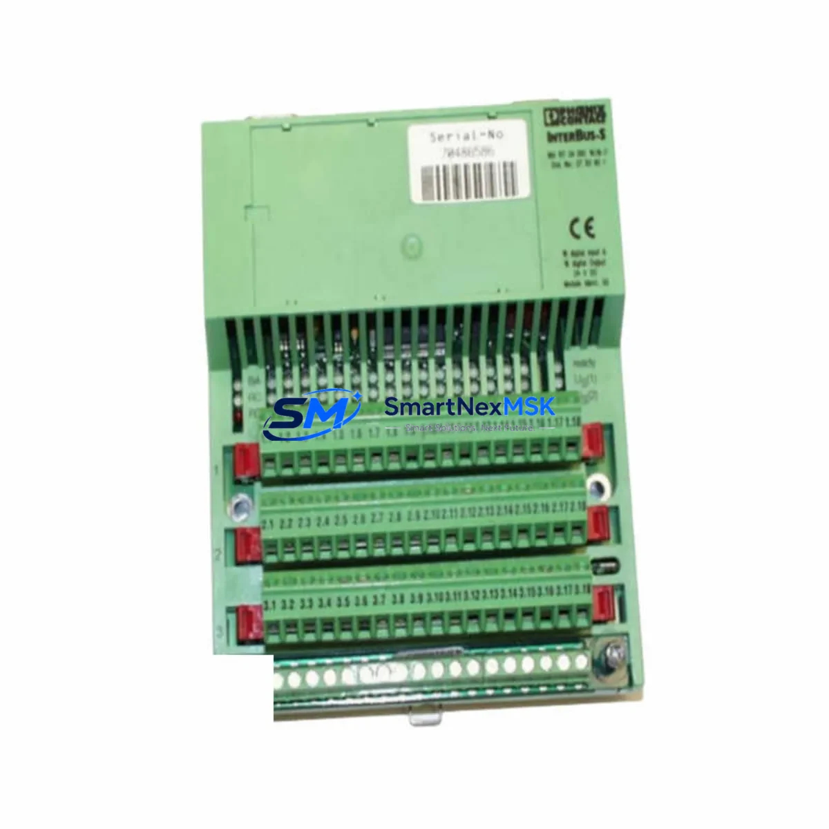
Phoenix Contact IBS RT 24DI0 16/16-T: Retrofit-Ready INTERBUS Remote Terminal for Legacy Control Systems
The Phoenix Contact IBS RT 24DI0 16/16-T is a 16-channel digital input / 16-channel digital output remote terminal module designed for INTERBUS fieldbus networks. As a retrofit-ready replacement for discontinued or aging INTERBUS I/O nodes, this module enables engineers to restore, upgrade, or expand existing control architectures without redesigning the entire control cabinet or rewriting PLC logic from scratch.
Whether you are recovering from an unplanned failure of an obsolete node, executing a planned line upgrade, or migrating a legacy INTERBUS-S installation to a current-generation INTERBUS topology, the IBS RT 24DI0 16/16-T provides a direct-fit solution with minimal commissioning overhead. Operating at 24 VDC, it integrates seamlessly into existing Phoenix Contact INTERBUS ring segments alongside other remote bus terminals and inline modules.
Upgrade Compatibility Table
| Parameter | IBS RT 24DI0 16/16-T Specification | Retrofit / Replacement Notes |
|---|---|---|
| Digital Inputs | 16 × 24 VDC | Verify field wiring terminal pitch matches existing node |
| Digital Outputs | 16 × 24 VDC, 0.5 A per channel | Confirm load current per channel does not exceed 0.5 A |
| Fieldbus Protocol | INTERBUS (IBS) remote bus | Compatible with INTERBUS-S and current INTERBUS ring topologies |
| Bus Connection | 9-pin D-Sub IN / OUT connectors | Reuse existing INTERBUS trunk cables; verify cable shielding continuity |
| Power Supply | 24 VDC (18–30 VDC), segment power via bus connector | Check cabinet PSU capacity; account for inrush current on startup |
| Installation | DIN rail (EN 60715 TS 35) | Direct mechanical replacement on standard 35 mm DIN rail |
| Module Address | Auto-assigned by INTERBUS master during ring scan | Confirm process data offset in PLC program matches ring position |
| Communication Compatibility | INTERBUS protocol, IBS master controllers | Compatible with ILC 150 ETH, ILC 350 PN, and legacy IBS master cards |
| Commissioning | PC Worx / Automation Builder / IBS CMD | Re-scan ring after replacement; verify I/O mapping in PLC project |
| Warranty | 12-Month Warranty — covers manufacturing defects; includes pre-shipment functional test | |
Retrofit Planning for Existing Automation Systems
Successful integration of the IBS RT 24DI0 16/16-T into a running production environment requires a structured pre-replacement audit. Begin by documenting the existing INTERBUS ring topology: record the physical order of all nodes, their process data lengths, and the corresponding I/O address assignments in the PLC program. This is especially critical when the failed or obsolete node sits mid-ring, as removing it will break the ring and halt all downstream communication until the replacement is installed and the ring is re-established.
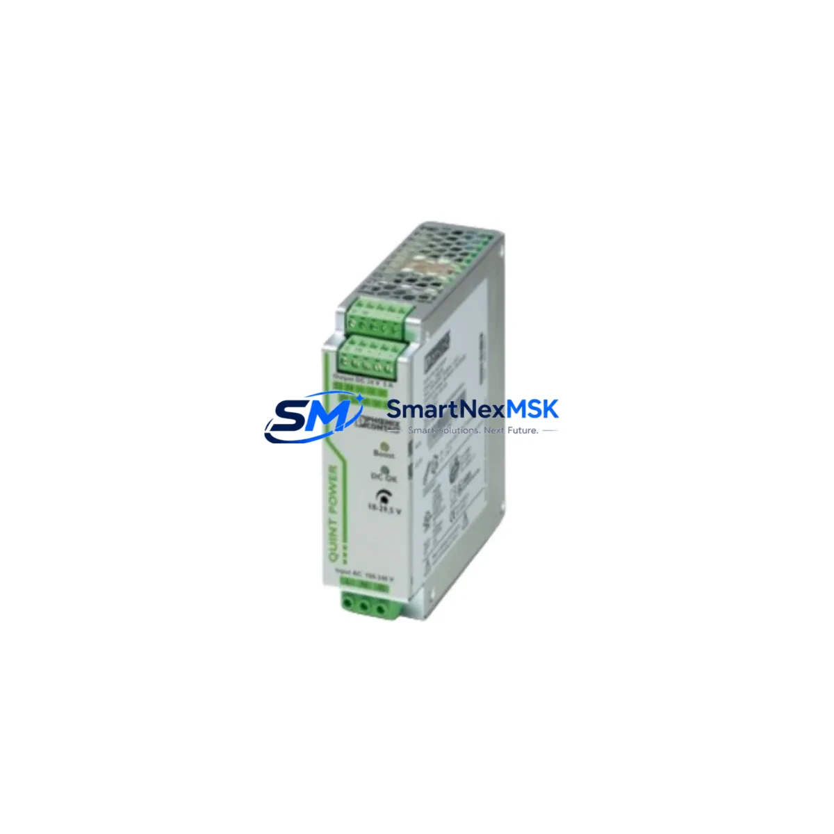
On the power side, verify that the cabinet’s 24 VDC power supply — often a Phoenix Contact QUINT-PS or TRIO-PS series unit — has sufficient residual capacity to support the replacement module’s current draw. The IBS RT 24DI0 16/16-T draws segment power through the INTERBUS bus connector, but field-side loads on the 16 output channels must be budgeted separately. If the existing PSU is already near its rated output, consider adding a secondary Phoenix Contact UNO-PS buffer module to protect against voltage sag during output switching transients.
Terminal wiring is the most time-sensitive step during a live-line retrofit. The IBS RT 24DI0 16/16-T uses a plug-in screw terminal block, which allows the field wiring connector to be pre-wired on the bench and then plugged into the replacement module without disturbing individual conductors. Cross-reference the original wiring diagram against the terminal assignment of the new module before powering up. Pay particular attention to the common (0 V) reference for the input group and the output supply rail — mismatched commons are a frequent source of commissioning faults in mixed-vendor retrofit scenarios.
For systems where the INTERBUS master is a legacy Phoenix Contact IBS ISA SC/I-T or IBS PCI SC/I-T master card, confirm that the installed version of IBS CMD or PC Worx supports the module’s firmware revision. In most cases, the IBS RT 24DI0 16/16-T is recognized automatically during the ring scan without requiring a manual device description file update. However, if the master controller is an older ILC 150 ETH or ILC 200 IB inline controller, verify the firmware version and update if necessary before performing the ring scan.
I/O expansion scenarios are also common in retrofit projects. If the upgrade plan calls for adding new I/O points beyond the capacity of the IBS RT 24DI0 16/16-T, consider inserting additional IBS RT 24 DIO 16/16-T nodes or Phoenix Contact Inline series modules — such as the IB IL 24 DI 16 or IB IL 24 DO 16 — into the ring at the same time. Combining the replacement and expansion into a single maintenance window minimizes total downtime and reduces the number of ring re-scans required.
HMI screens connected to the control system via Phoenix Contact VISU+ or third-party SCADA platforms should be reviewed for any I/O tag bindings that reference the replaced module’s process data address. If the new module occupies the same ring position as the original, the process data offset will be identical and no HMI changes are required. If the ring topology has changed — for example, due to the insertion of additional nodes — update the tag addresses in the HMI project and perform a full functional test before returning the line to production.
Downtime Control During System Migration
Minimizing unplanned downtime is the primary concern in any INTERBUS retrofit. The recommended approach is to pre-stage the replacement IBS RT 24DI0 16/16-T on a bench test rig before the maintenance window begins. Using a portable Phoenix Contact ILC 150 ETH or a laptop running PC Worx Express, perform a ring scan with the replacement module in isolation to confirm it is recognized correctly and that its process data length matches the original node. This pre-shipment verification step — combined with the 12-month warranty coverage provided with every unit — ensures that the module arriving on site is fully functional before the production line is taken offline.
During the actual swap, follow a structured sequence: isolate the segment power, disconnect the INTERBUS trunk cables from the failed node, remove the field wiring connector (which remains pre-wired), install the replacement module on the DIN rail, reconnect the trunk cables, reattach the field wiring connector, and restore segment power. The entire physical swap can typically be completed in under 15 minutes by a trained technician. After power restoration, trigger a ring scan from the PLC or master controller — using IBS CMD or the online diagnostic function in PC Worx — and verify that all nodes are recognized and that the process data map matches the saved project configuration.
To protect original PLC program logic during the migration, always upload and archive the current PLC project from the controller before beginning any hardware changes. Store the backup on a local engineering laptop as well as a network share. If the controller is an ILC 350 PN or ILC 390 PN, use the SD card backup function to create a complete controller image. This ensures that if the ring scan produces an unexpected configuration mismatch, the original program can be restored within minutes without requiring a full re-download from the engineering workstation.
For systems with tight production schedules, consider scheduling the retrofit during a planned shift changeover or a scheduled preventive maintenance window. Coordinate with the process control team to confirm that all interlocks and safety circuits remain active during the swap, and that the HMI operator is aware of the temporary I/O interruption. Document the completed retrofit in the plant’s maintenance management system, including the module serial number, installation date, and ring position, to support future troubleshooting and warranty claims.
Retrofit Support FAQ
Q1: Is the IBS RT 24DI0 16/16-T a direct drop-in replacement for the original Phoenix Contact INTERBUS remote terminal at the same ring position?
Yes. The IBS RT 24DI0 16/16-T uses the same INTERBUS remote bus protocol, identical process data length (16 DI + 16 DO = 32 bits), and the same DIN rail form factor as the original node. In most cases, the PLC program requires no modification provided the module is installed in the same ring position. Verify the process data offset in your PLC project after the ring scan to confirm the mapping is correct.
Q2: What commissioning steps are required after installing the replacement module?
After physical installation, restore segment power and trigger a ring scan from the INTERBUS master controller using IBS CMD or PC Worx. Confirm that the module is recognized at the correct ring position and that the process data length matches the project configuration. Perform a full I/O functional test — activate each output channel individually and verify the corresponding field device response, then check each input channel against its field sensor. Update the plant maintenance record with the module serial number and installation date.
Q3: How do I verify wiring compatibility before powering up the replacement module?
Before restoring power, use a continuity tester to verify that the plug-in terminal block wiring matches the original terminal assignment diagram. Confirm that the 0 V common reference for the input group is connected to the correct terminal, and that the output supply rail voltage is within the 18–30 VDC operating range. Check that the INTERBUS trunk cable shield is connected at one end only (typically at the master end) to avoid ground loops. If the original wiring diagram is unavailable, use IBS CMD to read the I/O status after power-up and cross-reference against the known field device states.
Q4: What does the 12-month warranty cover, and how is it claimed?
Every IBS RT 24DI0 16/16-T unit shipped by SMARTNEXMSK includes a 12-month warranty covering manufacturing defects and functional failures under normal operating conditions. Each unit undergoes a pre-shipment functional test to verify digital I/O operation and INTERBUS communication before dispatch. To claim warranty service, contact [email protected] with the module serial number, purchase order reference, and a description of the fault. Replacement units are dispatched from stock, and the defective unit is returned for inspection. Warranty does not cover damage resulting from incorrect wiring, overvoltage, or mechanical impact.
© 2026 SMARTNEXMSK. All rights reserved.
Original Source: https://smartnexmsk.com
Contact: [email protected] | +86 18259474341