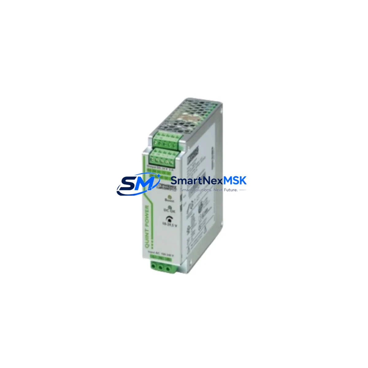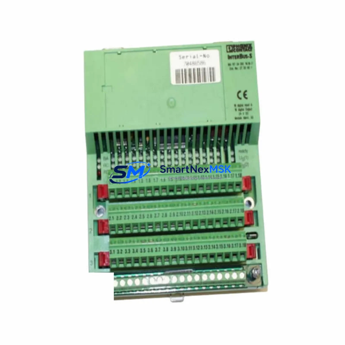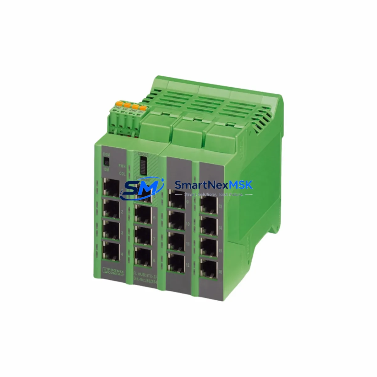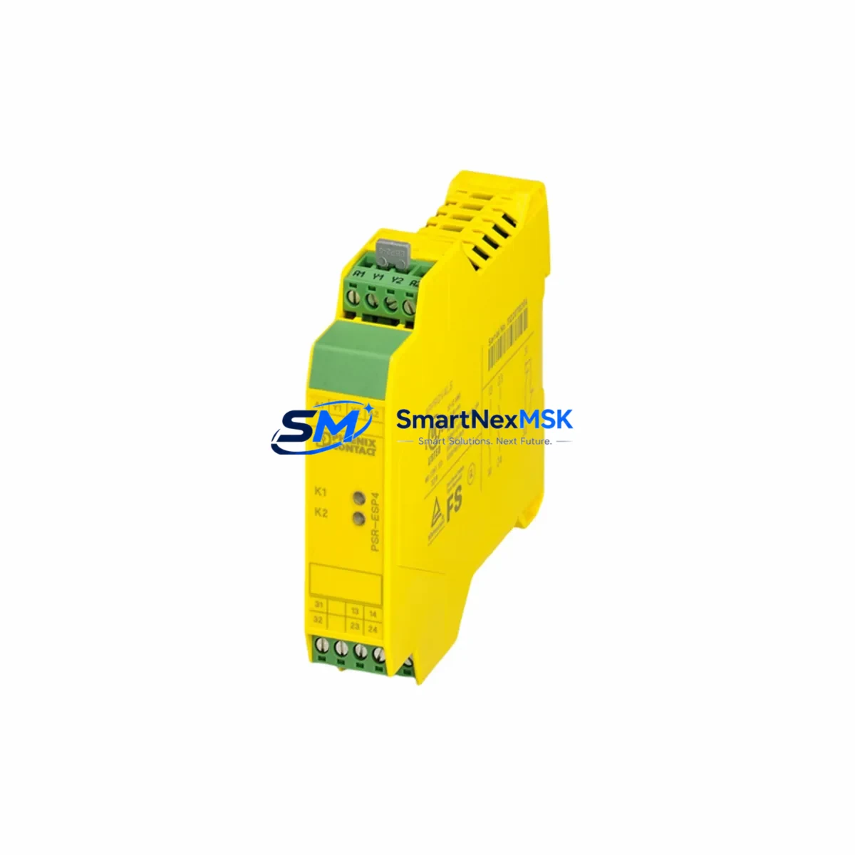
Phoenix Contact PSR-SCP-24DC/ESP4/2X1/1X2 Retrofit-Ready Safety Relay for PSR-SCP Series Control Systems
The Phoenix Contact PSR-SCP-24DC/ESP4/2X1/1X2 (Order No. 2981020) is a 24 VDC emergency-stop and safety-gate monitoring relay engineered for seamless integration into existing PSR-SCP series safety circuits. With four instantaneous safety contacts arranged in a 2×1 + 1×2 configuration, this module delivers SIL 3 / PLe-capable performance while maintaining the same DIN rail footprint and terminal layout as earlier PSR-SCP variants — making it the preferred drop-in replacement for aging or discontinued safety relay assemblies across a wide range of industrial control cabinets.
Whether you are modernizing a legacy machine guarding circuit, replacing a worn PSR-SCP-24DC/ESD/4X1/1X2 or PSR-SCP-24DC/ESP2/2X1/1X2 that has reached end-of-life, or expanding an existing safety zone to meet updated EN ISO 13849-1 requirements, the PSR-SCP-24DC/ESP4/2X1/1X2 provides a validated upgrade path with minimal rewiring and no PLC program modification.
Upgrade Compatibility Table
| Parameter | PSR-SCP-24DC/ESP4/2X1/1X2 (2981020) | Typical Legacy Module |
|---|---|---|
| Supply Voltage | 24 VDC (19.2–28.8 V) | 24 VDC |
| Safety Contacts | 4 NO (2×1 + 1×2 configuration) | 2–4 NO (varies by model) |
| Auxiliary Contact | 1 NC signaling output | 1 NC (confirm on legacy wiring diagram) |
| Safety Category | Cat. 4 / PLe / SIL 3 | Cat. 3–4 (verify legacy certification) |
| Mounting | 35 mm DIN rail (EN 60715) | 35 mm DIN rail — direct fit |
| Terminal Pitch | 5.08 mm screw terminals | 5.08 mm — no adapter required |
| Communication | Hardwired safety loop (dual-channel) | Hardwired — no protocol migration needed |
| Replacement Recommendation | Direct replacement for PSR-SCP-24DC/ESD/4X1/1X2 and similar | Verify contact count and reset mode |
| Commissioning Note | Manual or automatic reset selectable via jumper | Match reset mode to existing machine logic |
| Warranty | 12-Month Warranty — tested and verified before shipment | |
Retrofit Planning for Existing Automation Systems
A successful retrofit begins well before the module arrives on site. When replacing the PSR-SCP-24DC/ESP4/2X1/1X2 in an operational control cabinet, engineers should first audit the existing safety circuit documentation: confirm the dual-channel input wiring from the emergency-stop pushbutton or light curtain, verify the 24 VDC supply rail capacity — particularly if the cabinet also powers a PSR-MC50 monitoring relay or a PSR-SPP series speed monitoring module — and check that the DIN rail segment has adequate clearance for the module’s 22.5 mm width.
Terminal-by-terminal cross-referencing is essential. Map the A1/A2 coil supply, the S11/S12 and S21/S22 dual-channel input pairs, and the 13/14, 23/24, 33/34, and 41/42 output contacts against the original wiring diagram before disconnecting any conductors. If the legacy installation used a PSR-SCP-24DC/ESP2/2X1/1X2 with only two safety output pairs, confirm that the downstream safety PLC input card — such as a Pilz PNOZmulti 2 PNOZ m B0 or a Siemens ET 200SP F-DI module — can accept the additional contact channels without reconfiguration.
For cabinets that integrate the safety relay into a broader Phoenix Contact Inline or Axioline F I/O station, verify that the PSR-SCP-24DC/ESP4/2X1/1X2 feedback loop is correctly wired into the safety PLC’s EDM (External Device Monitoring) input. If the control system uses a Phoenix Contact RFC 470S PN 3TX safety controller or a comparable safety CPU, the EDM channel assignment in the safety program must match the physical wiring — no software change is required for a like-for-like replacement, but any contact count change demands a safety function validation.
Where the original cabinet included a PSR-TBUS DIN rail connector for potential distribution, confirm that the new module’s A1/A2 pins align with the bus segment. Cabinets that also house a QUINT POWER 24VDC/10A power supply should have their load calculation reviewed: adding or replacing safety relays can shift the total current draw, and the supply’s SFB (Static Free Boost) characteristic must still cover the inrush of all connected modules simultaneously.
If the retrofit scope extends to replacing a PSR-SCP-24DC/ESAM4/3X1/1X2 muting relay or integrating a new PSR-MS60 safety mat controller, plan the wiring changes in a single scheduled window to minimize the number of safety validation cycles required. All replacement modules supplied by SMARTNEXMSK are pre-tested against Phoenix Contact factory specifications and ship with a 12-month warranty, reducing the risk of commissioning delays caused by infant-failure components.
Downtime Control During System Migration
Minimizing unplanned downtime during a safety relay replacement requires a structured hot-swap protocol. Before de-energizing the safety circuit, photograph or scan the existing terminal wiring and label every conductor with its destination address. Use a portable 24 VDC bench supply to pre-test the PSR-SCP-24DC/ESP4/2X1/1X2 in isolation — verify that both input channels respond correctly, that all four safety output contacts close on energization, and that the auxiliary NC contact opens as expected. This bench verification, which takes approximately 15 minutes, eliminates the most common source of commissioning delays: a module fault discovered only after the cabinet is reassembled.
During the physical swap, keep the safety PLC in its current safe state rather than forcing outputs. If the machine control logic is managed by a Siemens S7-1500F or Allen-Bradley GuardLogix 5580, the safety program’s passivation behavior will hold all F-DO outputs in the safe state automatically while the safety relay is disconnected — no manual program modification is needed. Once the new module is wired and the cabinet door is closed, perform a full functional test of every safety function that routes through the relay: emergency stop, safety gate, two-hand control, or light curtain, as applicable. Document the test results in the machine’s safety logbook before returning the line to production.
For multi-zone safety architectures where the PSR-SCP-24DC/ESP4/2X1/1X2 feeds multiple machine zones through a PSR-SCP-24DC/ESP4/2X1/1X2 expansion relay or a zone-switching relay, sequence the replacement zone by zone to maintain partial production continuity. This approach, combined with pre-staged replacement modules from SMARTNEXMSK’s in-stock inventory, typically reduces total migration downtime to under two hours per safety zone.
Retrofit Support FAQ
Q1: Is the PSR-SCP-24DC/ESP4/2X1/1X2 (2981020) a direct replacement for the PSR-SCP-24DC/ESD/4X1/1X2?
A: In most applications, yes. Both modules share the same 24 VDC supply voltage, 35 mm DIN rail mounting, and 5.08 mm terminal pitch. The primary difference is the input circuit type: the ESP4 variant monitors emergency-stop devices with dual-channel input, while the ESD variant is optimized for enabling switch monitoring. Verify the input channel wiring and reset mode configuration before installation. If the contact count and terminal assignment match your existing wiring diagram, no rewiring is required.
Q2: Do I need to modify my safety PLC program after replacing this module?
A: For a like-for-like replacement where the contact count, reset mode, and EDM feedback wiring remain unchanged, no safety program modification is required. If you are upgrading from a 2-contact to a 4-contact configuration, the safety CPU’s EDM input assignment and the safety function’s output channel mapping must be reviewed and re-validated in accordance with your machine’s safety plan.
Q3: What commissioning tests are required after installation?
A: At minimum, perform a full functional test of every safety function routed through the relay: actuate each emergency-stop device and safety gate individually, verify that all four safety output contacts open within the specified response time (≤15 ms), confirm that the auxiliary NC contact signals correctly to the PLC, and test both manual and automatic reset modes as configured. Record all test results in the machine safety logbook. SMARTNEXMSK modules are pre-tested before shipment, but on-site functional validation is mandatory for safety-rated installations.
Q4: What does the 12-month warranty cover, and how is it claimed?
A: The 12-month warranty covers manufacturing defects and functional failures under normal operating conditions. Each module is tested against Phoenix Contact factory specifications before shipment. To claim warranty service, contact SMARTNEXMSK with your order number and a description of the fault. We will arrange priority replacement or repair to minimize your production impact. The warranty does not cover damage caused by incorrect wiring, overvoltage, or installation outside the module’s rated environmental conditions.
© 2026 SMARTNEXMSK. All rights reserved.
Original Source: https://smartnexmsk.com
Contact: [email protected] | +86 18259474341