ProSoft MVI56-DFCMR Retrofit-Ready DF1 Serial Module for ControlLogix Control Systems
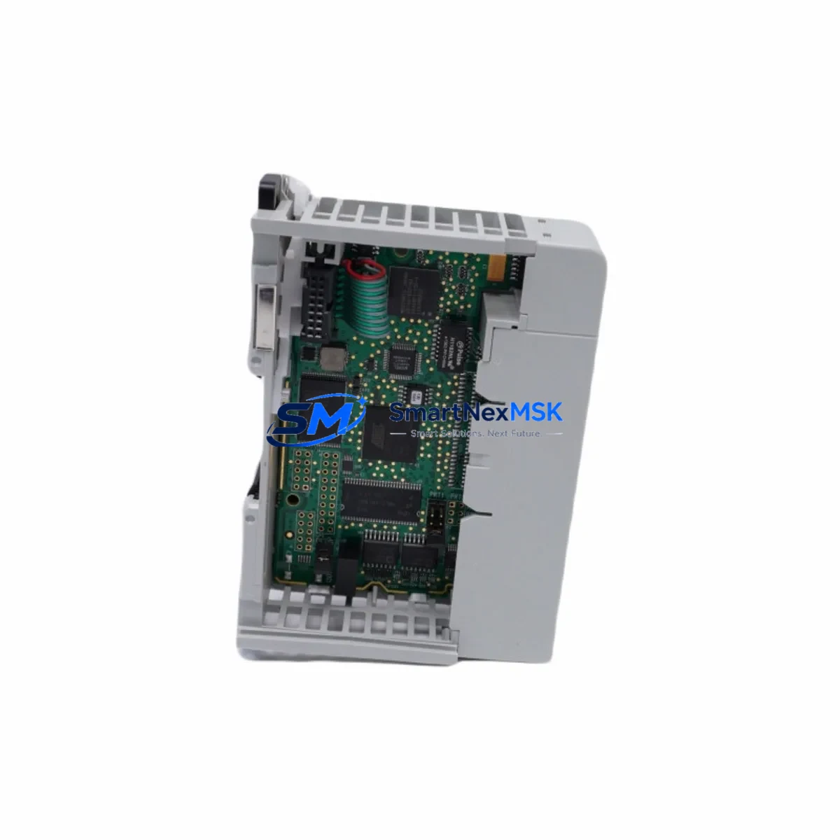
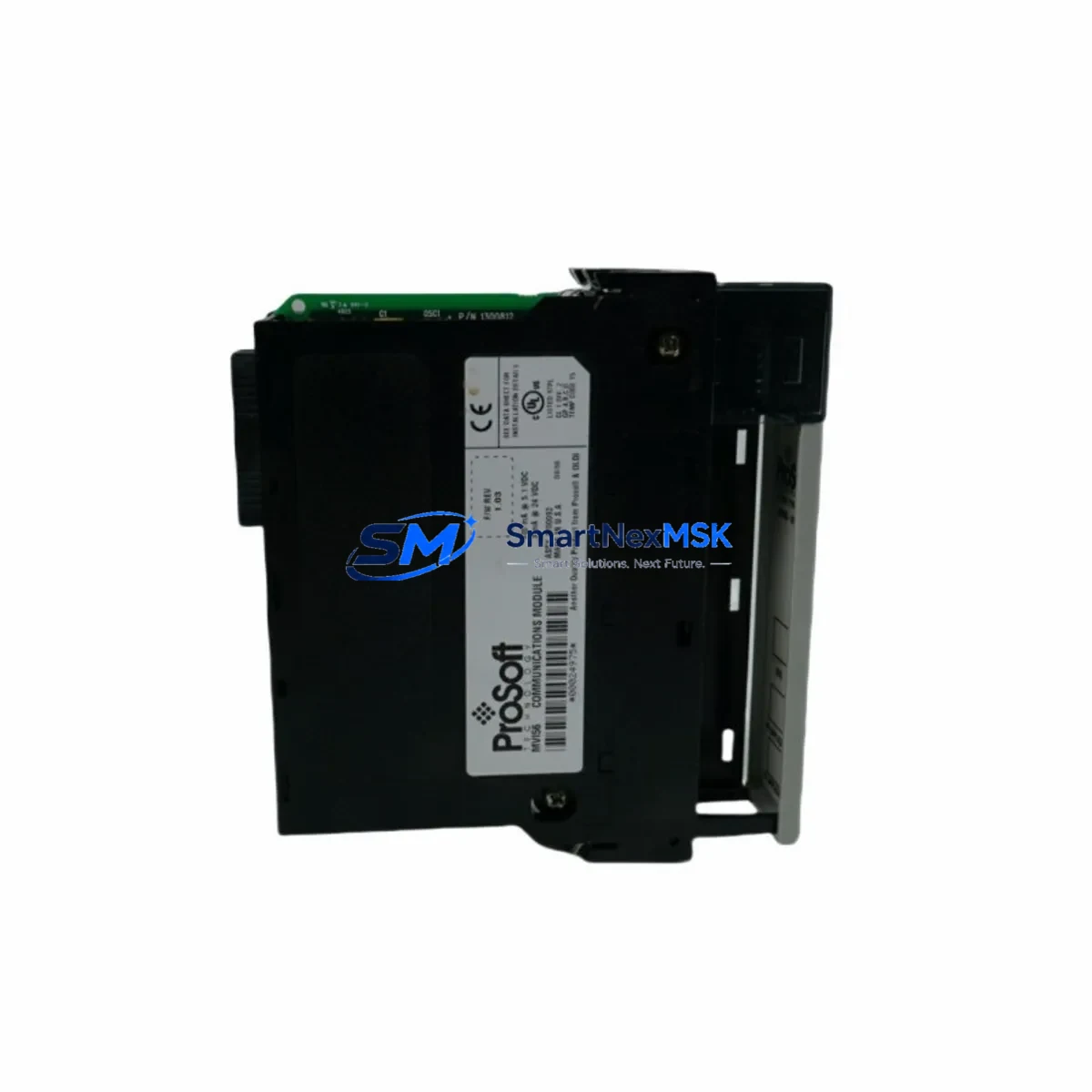
The ProSoft MVI56-DFCMR is a DF1 full-duplex serial communication module engineered for Allen-Bradley ControlLogix 1756 backplane platforms. Designed as a retrofit-ready replacement for legacy serial communication infrastructure, this module enables industrial facilities to modernize aging control architectures without replacing the entire PLC chassis or rewriting core ladder logic. Whether you are migrating from an older SLC 500 or PLC-5 serial network, upgrading a ControlLogix 1756-L55 or 1756-L61 controller environment, or restoring a discontinued communication path, the MVI56-DFCMR provides a validated, field-proven upgrade path with minimal disruption to production continuity.
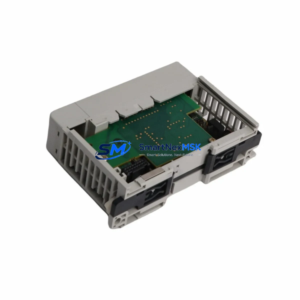
The module occupies a single slot in the ControlLogix 1756 chassis and communicates with the controller backplane via the standard 1756 backplane interface. It supports DF1 full-duplex and half-duplex master/slave protocols, making it directly compatible with legacy Allen-Bradley PLC-5 and SLC 500 serial networks that rely on RS-232 or RS-422/485 physical layers. For facilities operating mixed-generation control systems — where a newer ControlLogix controller must interface with older field devices, drives, or third-party instruments using DF1 — the MVI56-DFCMR eliminates the need for protocol converters or gateway hardware.
In retrofit projects, engineers frequently pair the MVI56-DFCMR with other ControlLogix platform components. The 1756-PA72 or 1756-PB72 power supply modules must be verified for adequate current capacity when adding communication modules to an existing chassis. The 1756-A7 or 1756-A13 chassis backplane must have an available slot, and module addressing must be confirmed in RSLogix 5000 or Studio 5000 to avoid I/O tree conflicts. If the existing project uses a 1756-ENBT or 1756-EN2T EtherNet/IP bridge module for remote I/O, the addition of the MVI56-DFCMR requires a slot reservation review and may affect the chassis power budget.
Terminal wiring adaptation is a critical step during installation. The MVI56-DFCMR uses a DB9 serial connector for RS-232 and screw-terminal connections for RS-422/485. When replacing an older 1756-MVI or third-party serial module, technicians must verify pin assignments, cable shielding, and ground references before powering the system. Incorrect wiring of the TX/RX/GND lines is the most common cause of communication faults during commissioning. ProSoft’s PCB (ProSoft Configuration Builder) software is used to configure the module’s port parameters, including baud rate, parity, stop bits, and protocol mode, and must be matched precisely to the legacy device settings.
Upgrade Compatibility Table
| Parameter | MVI56-DFCMR Specification | Retrofit Notes |
|---|---|---|
| Backplane Interface | ControlLogix 1756 (single slot) | Compatible with all 1756-Axxx chassis generations |
| Protocol Support | DF1 Full-Duplex, Half-Duplex Master/Slave | Direct replacement for legacy DF1 serial links |
| Physical Layer | RS-232 (DB9), RS-422/485 (screw terminal) | Verify cable pinout before wiring |
| Power Consumption | 800 mA @ 5 VDC (backplane) | Confirm chassis PSU headroom before installation |
| Configuration Tool | ProSoft Configuration Builder (PCB) | Match baud rate, parity, stop bits to legacy device |
| Controller Compatibility | 1756-L55, L61, L62, L63, L71, L72, L73, L74 | Firmware version ≥ v16 recommended |
| HMI Compatibility | PanelView Plus via ControlLogix tags | Update HMI tag references after module address change |
| Communication Link | Point-to-point and multi-drop DF1 | Verify node addressing for multi-drop topologies |
| Replacement Path | Replaces 1756-MVI, legacy ProSoft MVI56 variants | Review I/O tree and module slot assignment in Studio 5000 |
| Warranty | 12 Months | Covered from date of shipment; includes DOA replacement |
Retrofit Planning for Existing Automation Systems
Successful integration of the MVI56-DFCMR into an existing control system requires a structured pre-installation audit. Begin by documenting the current chassis layout, including the slot positions of all installed modules such as the 1756-IB16 digital input modules, 1756-OB16E digital output modules, 1756-IF8 analog input modules, and any existing 1756-DNB DeviceNet bridge or 1756-RIO Remote I/O modules. Slot conflicts must be resolved before the new module is physically installed.
Power budget verification is non-negotiable. The 1756-PA72 power supply provides 10A at 5 VDC to the backplane. Adding the MVI56-DFCMR’s 800 mA draw to the existing load must be calculated against the total chassis consumption. If the chassis is already near capacity, a second power supply or chassis expansion using a 1756-A4 extension chassis may be required.
For facilities migrating from a PLC-5 or SLC 500 platform entirely, the MVI56-DFCMR serves as the serial communication bridge during the transition period, allowing the new ControlLogix controller to maintain DF1 communication with legacy field devices — including variable frequency drives, weigh scales, barcode readers, and third-party instruments — while the broader migration is completed in phases. This phased approach is strongly recommended to avoid full production shutdowns.
Program compatibility must be verified in Studio 5000. The module’s configuration data table, MSG instruction parameters, and produced/consumed tag structures must be reviewed against the original RSLogix 5000 project. If the original project used an older ProSoft MVI56-DF1 module, the tag mapping may differ slightly and require remapping in the controller program. A 1747-PIC or 1784-U2DHP programming cable may be needed for legacy device access during the transition.
HMI screen updates are often overlooked in retrofit projects. If the facility uses a PanelView Plus 6 or PanelView Plus 7 terminal connected to the ControlLogix controller via EtherNet/IP, any tag references tied to the old module’s data table must be updated in FactoryTalk View Studio to reflect the new MVI56-DFCMR tag structure. Failure to update HMI references will result in communication fault alarms on the operator panel after the module swap.
Downtime Control During System Migration
Minimizing unplanned downtime is the primary concern in any live system retrofit. The recommended approach for MVI56-DFCMR installation is a planned maintenance window of 2–4 hours, during which the ControlLogix controller is placed in Program mode, the existing serial module is removed, and the MVI56-DFCMR is installed and configured using ProSoft Configuration Builder before the controller is returned to Run mode.
Prior to the maintenance window, the complete Studio 5000 project should be backed up, the existing module configuration exported, and the MVI56-DFCMR pre-configured offline using PCB software. All wiring adapters, terminal blocks, and cable assemblies should be prepared and labeled in advance. This preparation reduces in-window installation time to under 60 minutes in most cases.
To protect original program logic, the controller program should never be modified during the physical swap. Only the I/O configuration tree and MSG instruction parameters should be updated to reference the new module slot and tag structure. The original ladder logic rungs, function block diagrams, and structured text routines should remain unchanged. This approach ensures that if the new module fails commissioning, the original program can be restored and the legacy module reinstalled without data loss.
For critical continuous-process applications where even a 2-hour window is unacceptable, a parallel installation strategy can be employed: install the MVI56-DFCMR in an adjacent chassis slot while the legacy module remains active, configure and test the new module’s communication path in shadow mode, then perform a hot-cutover during a brief process pause. This strategy requires an available chassis slot and careful MSG instruction management to avoid duplicate communication conflicts.
Retrofit Support FAQ
Q1: Is the MVI56-DFCMR a direct drop-in replacement for the original ProSoft MVI56-DF1?
A: The MVI56-DFCMR is functionally compatible with the MVI56-DF1 and supports the same DF1 full-duplex and half-duplex protocols. However, the internal data table structure and PCB configuration file format differ between generations. Engineers should review the tag mapping in Studio 5000 and update MSG instruction parameters accordingly. A direct slot swap is physically possible, but a program review is always recommended before returning the system to Run mode.
Q2: What wiring changes are required when replacing a legacy serial module?
A: The MVI56-DFCMR uses a DB9 connector for RS-232 and a 3-wire screw terminal for RS-422/485. If the legacy module used a different connector type or pinout, a wiring adapter or new cable assembly will be required. Always verify TX, RX, and GND assignments against the field device documentation before powering the system. Incorrect wiring is the leading cause of PORT FAULT errors during initial commissioning.
Q3: How is compatibility with third-party field devices verified before shipment?
A: Each MVI56-DFCMR unit shipped by SMARTNEXMSK undergoes a functional communication test using a DF1 loopback fixture prior to dispatch. The module is verified for backplane recognition, port initialization, and basic DF1 frame exchange. Customers are encouraged to provide their device baud rate, parity, and protocol mode settings in advance so that the module can be pre-configured before shipment, reducing on-site commissioning time.
Q4: What does the 12-month warranty cover?
A: The 12-month warranty covers manufacturing defects, backplane interface failures, and port communication hardware faults under normal operating conditions. It does not cover damage resulting from incorrect wiring, overvoltage, or installation in environments outside the module’s rated temperature and humidity range. DOA (Dead on Arrival) units are replaced within 5 business days of confirmed fault diagnosis. Warranty claims are processed through sales@smartnexmsk.com with proof of purchase and a fault description.
© 2026 SMARTNEXMSK. All rights reserved.
Original Source: https://smartnexmsk.com
Contact: sales@smartnexmsk.com | +86 18259474341