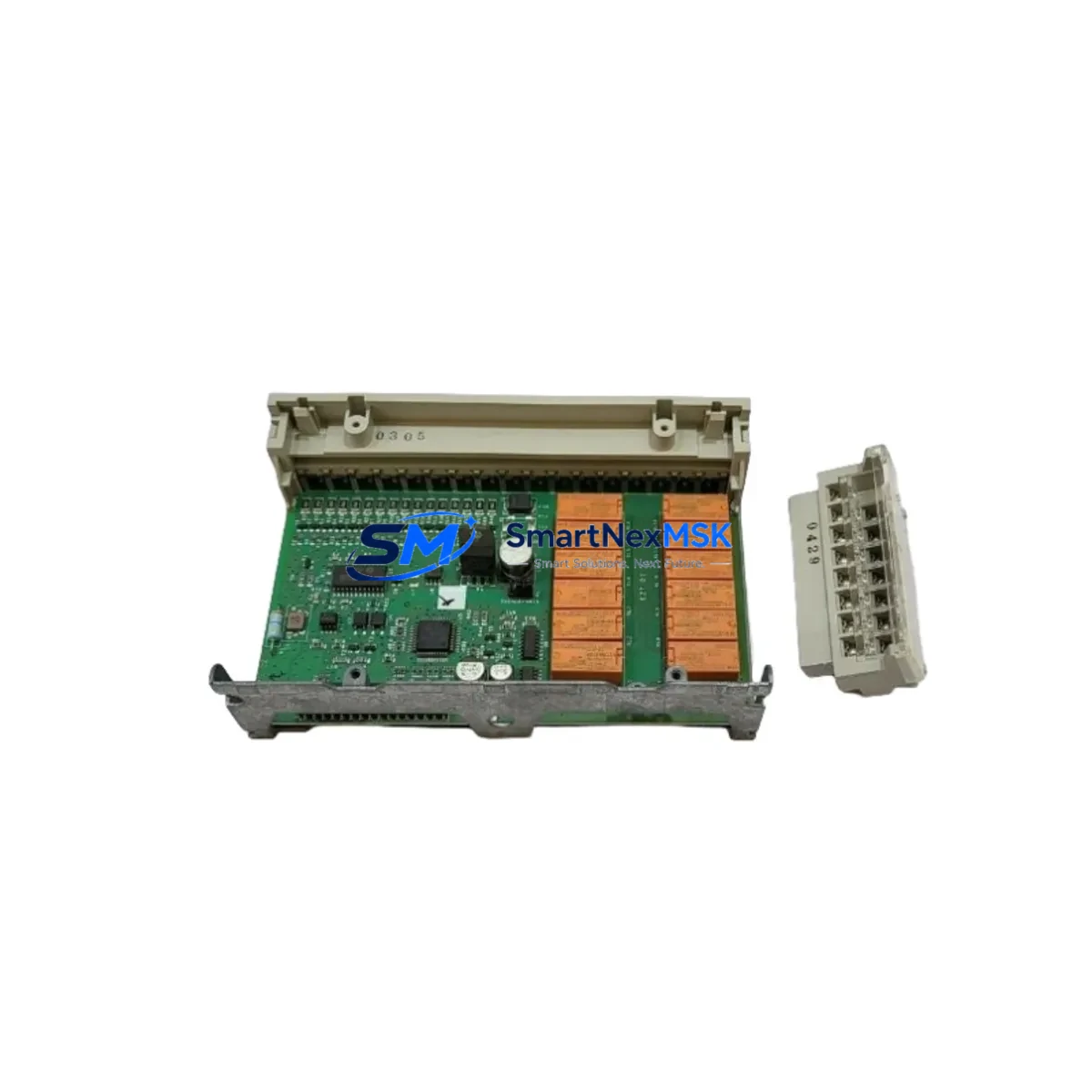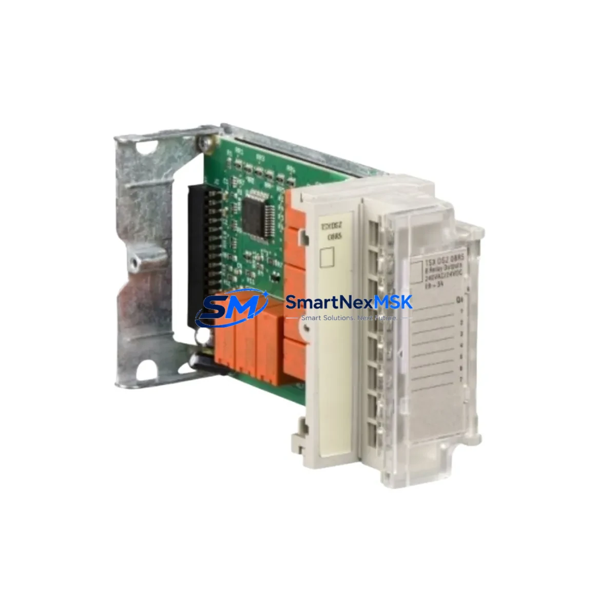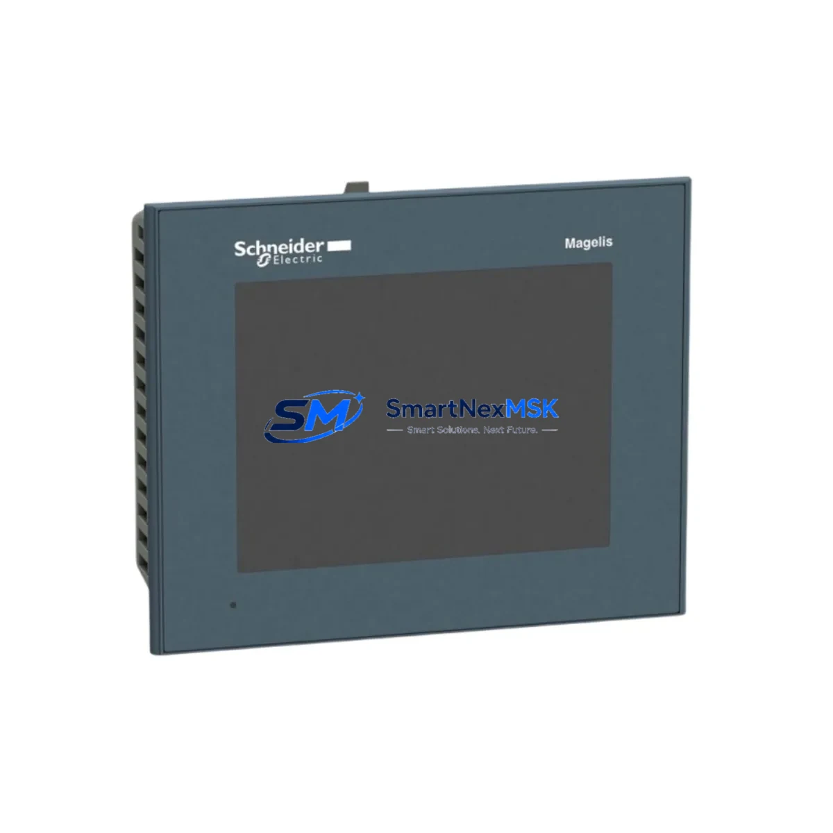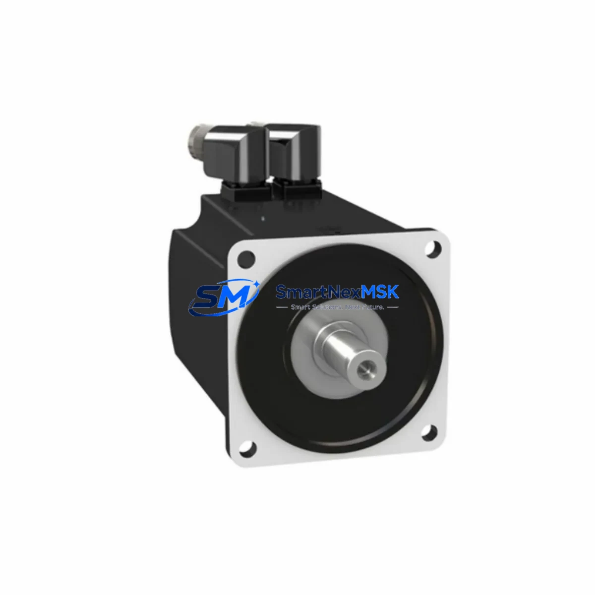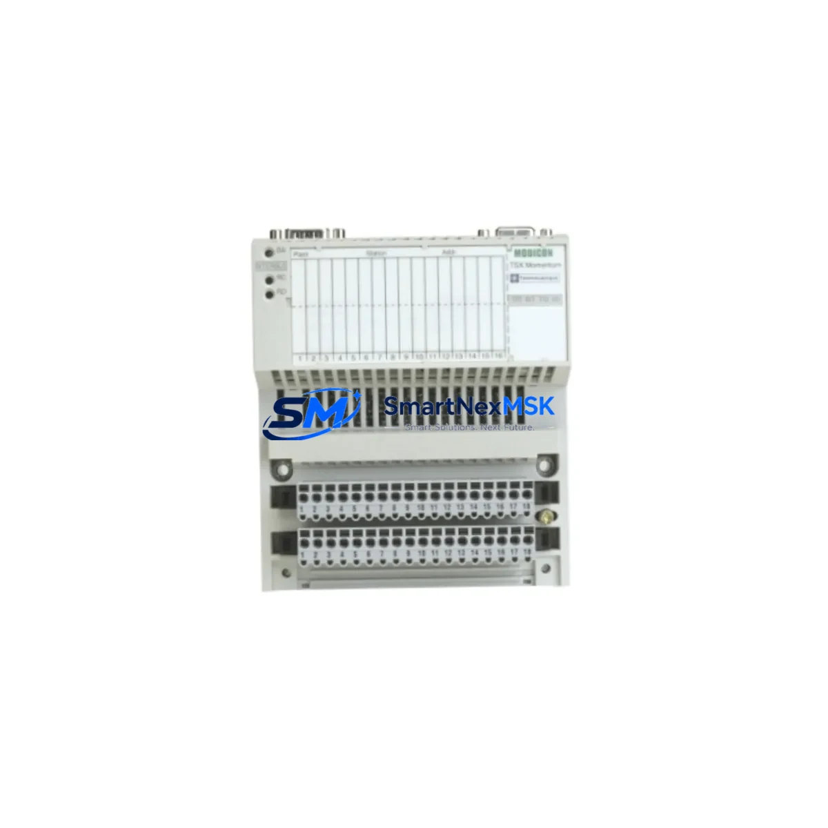
Schneider Electric 170INT11000 Maintenance-Ready Spare for Momentum Automation
The Schneider Electric 170INT11000 is an original Interbus communication adapter designed for the Modicon Momentum platform — one of the most widely deployed distributed I/O and controller architectures in industrial automation. For maintenance engineers managing aging control systems, this module represents a critical spare: its failure directly interrupts fieldbus communication between the Momentum CPU or I/O base and the Interbus network, triggering unplanned downtime across the entire segment.
Sourced from authorized supply channels and tested prior to shipment, the 170INT11000 offered through SMARTNEXMSK is an original Schneider Electric component — not a clone or refurbished substitute. Each unit undergoes functional verification before dispatch and is backed by a 12-month warranty, giving procurement and maintenance teams confidence in both quality and long-term supply continuity.
Whether you are executing a planned shutdown replacement, responding to a fieldbus fault alarm, or building a strategic spare parts buffer for a Momentum-based control cabinet, the 170INT11000 is a direct fit with no firmware reconfiguration required when replacing a like-for-like unit in the same Momentum base slot.
Spare Maintenance Table
| Parameter | Specification / Value |
|---|---|
| Part Number (SKU) | 170INT11000 |
| Brand | Schneider Electric |
| Series | Modicon Momentum |
| Module Type | Interbus Communication Adapter |
| Fieldbus Protocol | Interbus (IBS) |
| Compatible Bases | Modicon Momentum I/O Bases (170 Series) |
| Installation Method | Snap-on adapter to Momentum base — no tools required |
| Power Supply | Supplied via Momentum base backplane |
| Operating Temperature | 0°C to +60°C |
| Storage Temperature | -25°C to +70°C |
| Humidity | 5% to 95% non-condensing |
| Origin | France |
| Weight | 420 g |
| Compatibility | Direct replacement for existing 170INT11000 in Momentum systems |
| Firmware | No reconfiguration required for like-for-like replacement |
| Pre-shipment Testing | Functional verification performed on every unit |
| Warranty | 12 Months — covers manufacturing defects and functional failure |
| Typical Application | Distributed I/O fieldbus communication in Momentum control cabinets |
| Maintenance Recommendation | Inspect connector pins and bus termination annually; replace on first sign of CRC errors or bus fault LED |
Maintenance Planning for Continuous Operation
When a 170INT11000 Interbus adapter fails or is flagged during a control cabinet inspection, experienced maintenance engineers know that the fault rarely exists in isolation. The Interbus segment connects multiple nodes in a ring topology — a single adapter fault can cascade into a full segment dropout, taking down all downstream I/O stations simultaneously.
During a planned replacement of the 170INT11000, the following components in the same Momentum control cabinet should be inspected or held as concurrent spares:
- Momentum CPU Adapter (e.g., 170AAO92100 or 170ADM35010) — verify the CPU adapter is not generating bus errors independently; a degraded CPU adapter can mimic an Interbus communication fault.
- Momentum I/O Bases (170 Series) — inspect the base connector interface where the 170INT11000 snaps in; worn or oxidized contacts cause intermittent communication loss that is often misdiagnosed as an adapter failure.
- 24 VDC Power Supply Module — Momentum bases require stable 24 VDC bus power. Voltage sags below 20.4 VDC can cause the Interbus adapter to drop off the network. A dedicated power supply module with adequate current margin should be verified.
- Interbus Bus Terminal and Termination Resistor — the Interbus ring must be properly terminated at the last node. A missing or damaged termination resistor causes reflection errors that degrade all nodes on the segment, not just the one with the faulty adapter.
- Modicon Momentum Analog I/O Modules (e.g., 170AAI03000, 170AAO92100) — if the Interbus segment carries analog signals, verify that analog I/O modules on the same ring are not generating excessive noise or drawing excess current that stresses the adapter.
- Digital I/O Modules (e.g., 170ADI34000, 170ADO35400) — inspect digital I/O modules on the same Interbus segment for wiring faults, short circuits, or blown output channels that may have contributed to the adapter fault.
- Signal Isolators and Surge Protectors — in environments with heavy motor loads or frequent switching, signal isolators on fieldbus lines protect communication adapters from transient damage. Verify these are in place and functional.
- Fuse and Circuit Protection — check fuses on the 24 VDC supply rail feeding the Momentum base. A blown fuse on the bus power rail is a common root cause of apparent communication adapter failures.
- Interbus Master Controller Card — if the 170INT11000 is a slave adapter, verify the Interbus master (typically a PCI or rack-mounted master card in the host PLC or PC) is not generating bus reset commands due to its own fault or configuration mismatch.
- Communication Cables and Connectors — Interbus uses a specific 9-pin D-sub connector and shielded cable. Inspect cable shielding continuity, connector pin integrity, and cable routing away from high-voltage conductors.
Holding one spare 170INT11000 per Momentum Interbus segment — alongside a spare CPU adapter and a set of I/O module fuses — is a proven strategy for reducing mean time to repair (MTTR) in facilities where Momentum systems are still in active production service.
Site Replacement Workflow
Replacing the 170INT11000 on-site is a straightforward procedure that does not require specialized tools, but it must be executed with care to avoid damaging the Momentum base connector or disrupting adjacent nodes on the Interbus ring.
Step 1 — Isolate the segment: Before removing the adapter, notify the control system operator and place the affected Interbus segment in a safe state. Do not hot-swap the adapter without confirming the system supports hot-swap operation for this specific base configuration.
Step 2 — Document the current configuration: Record the node address, baud rate setting, and any DIP switch positions on the existing 170INT11000. Photograph the wiring and connector orientation before disconnection.
Step 3 — Remove the faulty adapter: Release the locking tabs on the Momentum base and slide the adapter out. Inspect the base connector for bent pins or debris before installing the replacement.
Step 4 — Install the 170INT11000 replacement: Align the new adapter with the base connector and press firmly until the locking tabs engage. Reconnect the Interbus cable to the adapter’s D-sub connector, ensuring the termination resistor is correctly positioned if this is the last node on the ring.
Step 5 — Power up and verify: Restore power to the segment and observe the adapter’s status LEDs. A solid green RUN LED and no active BUS FAULT LED indicate successful communication. Verify all downstream I/O nodes have returned to normal status in the SCADA or HMI display.
Step 6 — Update maintenance records: Log the replacement date, the serial number of the removed unit, and the new unit’s details in the plant maintenance system (CMMS). Schedule the next inspection interval based on the operating environment.
This workflow applies equally to emergency replacements during unplanned downtime and to scheduled replacements during planned maintenance windows. The 170INT11000’s plug-and-play compatibility with existing Momentum bases means that a trained technician can complete the physical replacement in under 15 minutes, with system restoration typically achieved within 30 minutes including verification.
Spare Parts Support FAQ
Q1: Is the 170INT11000 still available as a new original part, or is it only available as refurbished stock?
The 170INT11000 is available as an original Schneider Electric component through authorized spare parts distributors including SMARTNEXMSK. While Schneider Electric has transitioned many Momentum-series products to end-of-life status, original new-old-stock (NOS) and factory-tested units remain available through specialist industrial spare parts suppliers. Each unit sold by SMARTNEXMSK is functionally verified before shipment and covered by a 12-month warranty.
Q2: How do I confirm compatibility before ordering the 170INT11000 for my Momentum system?
Compatibility is confirmed by matching the fieldbus protocol (Interbus) and the Momentum base model number. The 170INT11000 is designed for Modicon Momentum 170-series bases configured for Interbus communication. If you are unsure of your base model or current adapter type, provide your existing adapter’s part number or a photo of the installed unit to our technical team at [email protected] for pre-order compatibility verification.
Q3: What is the recommended spare parts inventory strategy for facilities running multiple Momentum Interbus segments?
Industry best practice for facilities with three or more Momentum Interbus segments is to maintain a minimum of one 170INT11000 spare per five segments, with a floor of one unit regardless of segment count. For critical production lines where downtime cost exceeds USD 10,000 per hour, a one-to-one spare ratio per segment is recommended. Combine this with a spare CPU adapter and a set of I/O module fuses to cover the most common failure modes without overstocking.
Q4: What does the 12-month warranty cover, and what is the claims process?
The 12-month warranty covers manufacturing defects and functional failure under normal operating conditions. It does not cover damage caused by incorrect installation, overvoltage events, or physical impact. To initiate a warranty claim, contact [email protected] with your order number, a description of the fault, and photos of the installed unit and any visible damage. SMARTNEXMSK will arrange return shipping and either repair or replace the unit within the warranty period.
© 2026 SMARTNEXMSK. All rights reserved.
Original Source: https://smartnexmsk.com
Contact: [email protected] | +86 18259474341