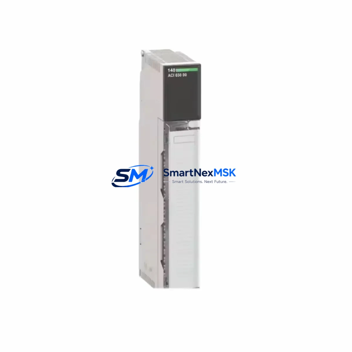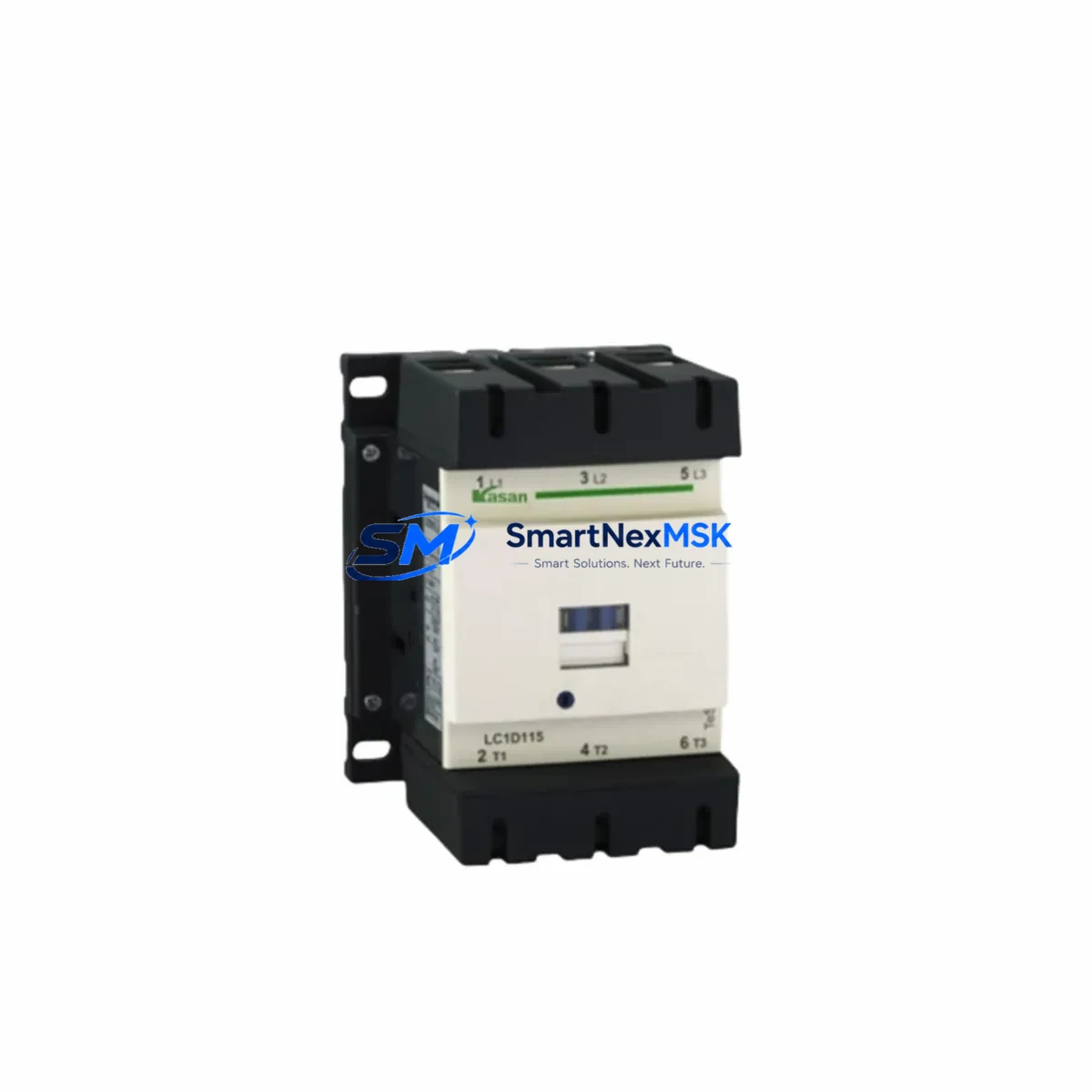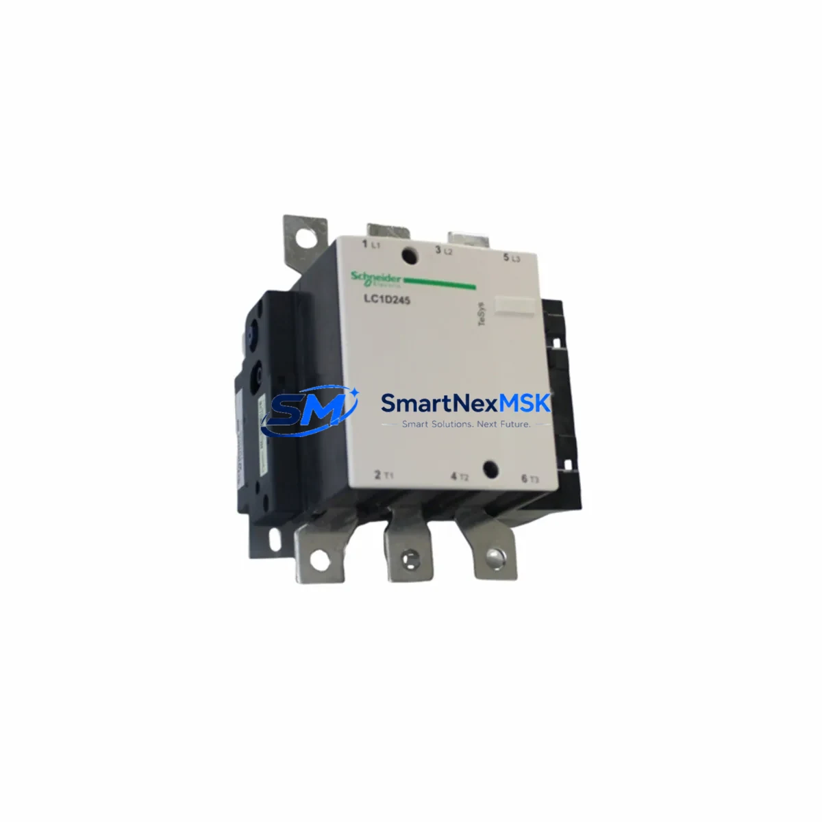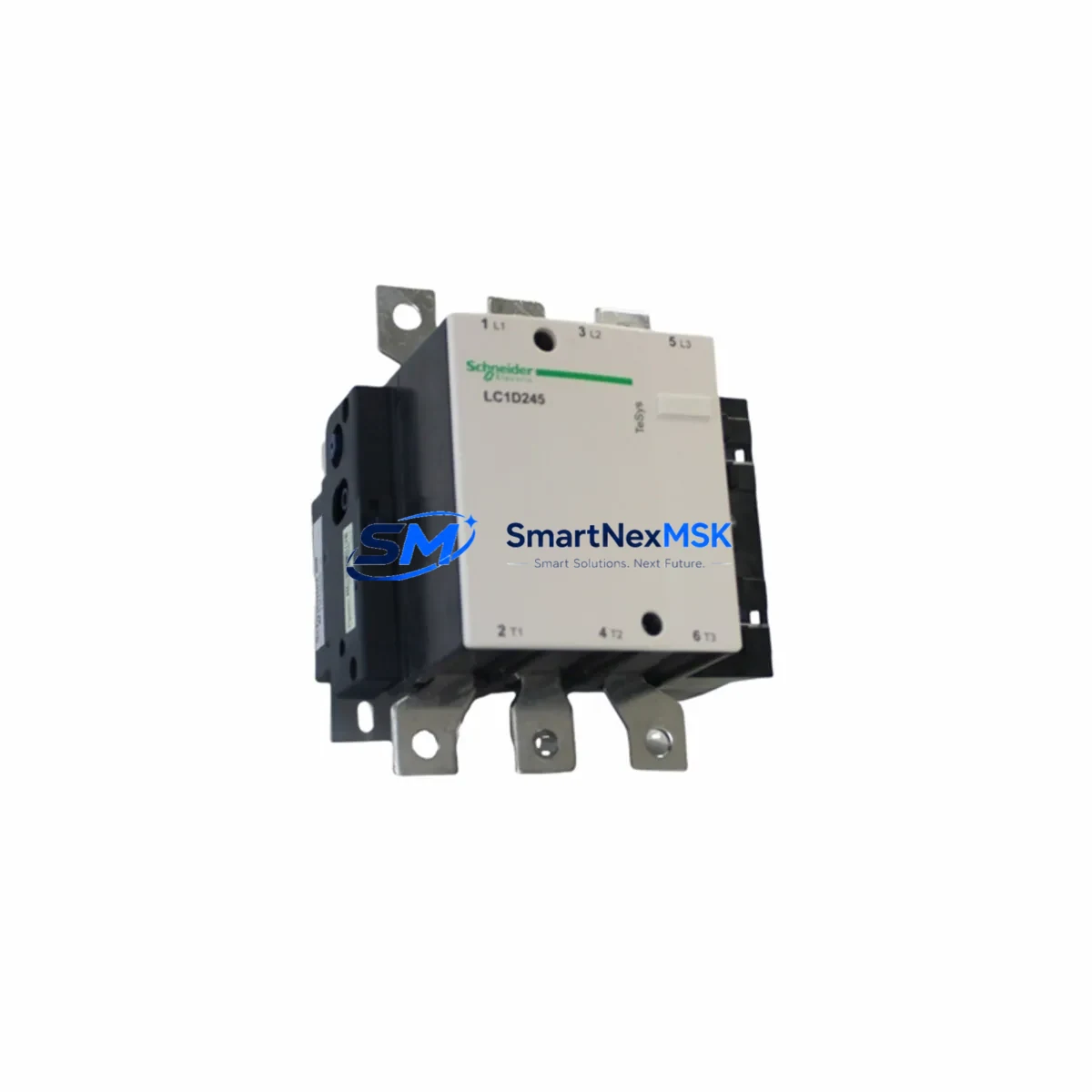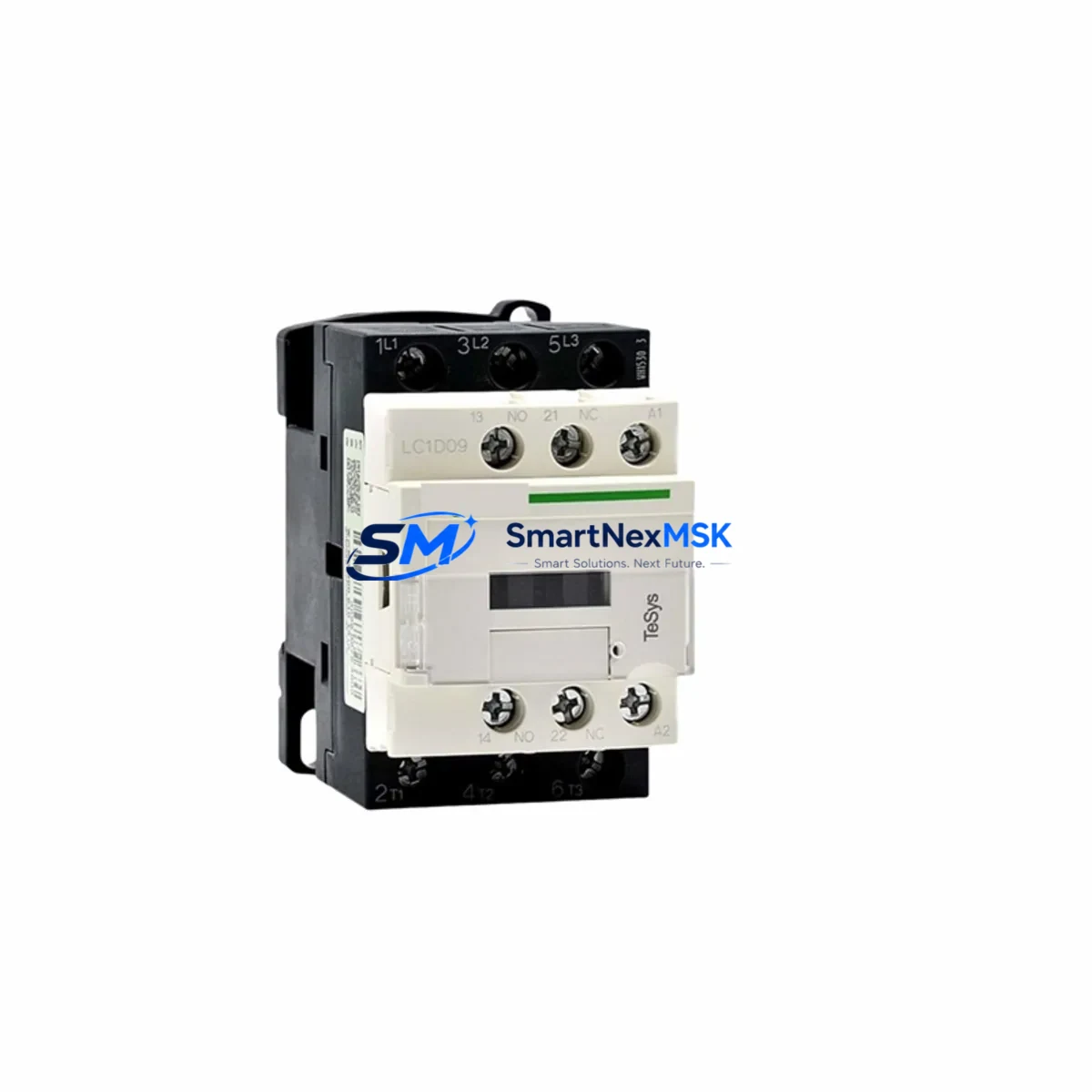
Schneider LC1D09M7C Retrofit-Ready Contactor for TeSys D Control Systems
The Schneider Electric LC1D09M7C is a 9A, 3-pole AC contactor from the TeSys D series, engineered for seamless integration into legacy motor control centers, control cabinets, and automation panels. As a retrofit-ready replacement, the LC1D09M7C is the preferred choice for engineers and maintenance teams modernizing aging electrical infrastructure without full system redesign. With a 220V AC coil (M7 suffix), DIN rail or panel-mount compatibility, and IEC 60947-4-1 compliance, this contactor delivers reliable performance in both new installations and direct drop-in replacement scenarios.
Whether you are replacing a failed LC1D09 unit, upgrading from an older LC1D06 or LC1D12 contactor, or migrating a legacy Telemecanique CA2-DN or CA3-DN auxiliary contactor circuit to the current TeSys D platform, the LC1D09M7C provides a verified, code-compliant upgrade path. Its compact footprint and standardized terminal layout minimize rewiring effort and reduce panel downtime during changeover.
Upgrade Compatibility Table
| Parameter | LC1D09M7C Specification | Retrofit Notes |
|---|---|---|
| Rated Current (AC-3) | 9A @ 400V | Direct replacement for LC1D09 variants |
| Coil Voltage | 220V AC / 50-60Hz (M7) | Verify existing coil voltage before swap; M5=110V, M7=220V, Q7=380V |
| Poles | 3-pole main + auxiliary | Add LA1DN11 or LA1DN22 auxiliary contact block for expanded I/O |
| Mounting | DIN rail (EN 60715) / screw panel | Compatible with existing TeSys D rail positions; no bracket change needed |
| Terminal Type | Screw clamp, 1–10mm² | Existing wiring reusable; confirm torque spec 1.2–1.5 N·m |
| Communication Compatibility | Standalone / TeSys T integration | Pair with LTM R motor management relay for Modbus RTU or EtherNet/IP monitoring |
| Replacement Path | LC1D06, LC1D09, CA2-DN, CA3-DN | Verify auxiliary contact arrangement before removal |
| Commissioning Focus | Coil energization, contact closure, interlock logic | Test NO/NC auxiliary contacts; confirm PLC input signal integrity |
| Warranty | 12 Months | Covered from date of shipment; includes functional test certificate |
Retrofit Planning for Existing Automation Systems
Successful integration of the LC1D09M7C into an existing control system requires a structured pre-installation review. Begin by auditing the control cabinet layout: confirm the available DIN rail space, verify the busbar configuration, and check whether the existing LC1D09 or LC1D06 contactor shares a mechanical interlock assembly with an adjacent unit. In reversing starter configurations, two contactors are typically interlocked using a LAD9R1 mechanical interlock kit — confirm this accessory is retained or replaced during the swap.
Next, review the power supply capacity. The LC1D09M7C coil draws approximately 7–10 VA at 220V AC during inrush. If the control transformer or SMPS (such as an ABL8 series power supply) is already near capacity due to added I/O modules or HMI panels, recalculate the total VA budget before energizing. In cabinets running a Modicon M221 or M241 PLC alongside multiple contactors, coil inrush can cause voltage dips that trigger false input reads — adding a surge suppressor module (LAD4RCU or LAD4RC) across the coil terminals is strongly recommended.
For systems using a TeSys T LTM R motor management relay, the LC1D09M7C integrates directly into the existing wiring harness. The LTM R communicates via Modbus RTU or EtherNet/IP, enabling remote monitoring of contactor state, overload trips, and phase imbalance — eliminating the need for separate auxiliary contact wiring back to the PLC rack. If the legacy system used a GV2ME or GV3ME manual motor starter in series with the contactor, verify that the upstream protection device’s trip curve remains coordinated with the new contactor’s rated Ith.
In I/O expansion scenarios — for example, when adding a TM3 expansion module to a Modicon M221 controller — the additional digital outputs driving contactor coils must be mapped correctly in the PLC program. Export and archive the existing .STO project file from SoMachine Basic or EcoStruxure Machine Expert before any hardware change. This ensures the original rung logic, output coil addresses, and timer presets are preserved and can be restored if commissioning reveals address conflicts.
HMI screens built on Magelis HMIGTO or HMISTO panels that display contactor status via discrete input bits should be validated post-swap. If the replacement contactor’s auxiliary contact block (LA1DN11) is wired to a different PLC input address than the original, update the HMI variable table accordingly. Communication links between the HMI and PLC — whether via Modbus serial, CANopen, or Ethernet — should be verified live before returning the system to production.
Downtime Control During System Migration
Minimizing unplanned downtime during a contactor replacement requires preparation before the panel is de-energized. Print or export the existing wiring diagram and photograph all terminal connections on the outgoing LC1D09 or LC1D06 unit. Label each wire with terminal markers before removal — this is especially critical in multi-contactor assemblies where L1/L2/L3 and T1/T2/T3 terminals are closely spaced.
Isolate the circuit at the upstream MCCB or fuse-switch disconnector (such as a TeSys GS1 or GS2 series fusible disconnect). Lock out and tag out (LOTO) per site safety procedures. With the LC1D09M7C pre-wired on a bench or spare DIN rail section, the physical swap can typically be completed in under 20 minutes for a standard 3-pole motor circuit. Reconnect auxiliary control wiring (A1/A2 coil terminals, 13/14 NO auxiliary) referencing the archived wiring diagram.
After reconnection, perform a cold functional test: energize the coil at reduced voltage if a variac is available, confirm main contact closure with a continuity tester, and verify auxiliary contact state changes are correctly read by the PLC. Only then restore full line voltage and run the motor through a start-stop cycle under no-load conditions before returning to full production load. This staged commissioning approach protects both the new contactor and the downstream motor from damage caused by wiring errors.
For critical production lines where even a 30-minute outage is unacceptable, pre-stage a fully wired spare LC1D09M7C on a plug-in terminal block assembly. This allows hot-swap replacement in under 5 minutes once the circuit is isolated, dramatically reducing mean time to repair (MTTR) and protecting production continuity.
Retrofit Support FAQ
Q1: Is the LC1D09M7C a direct drop-in replacement for the LC1D09BL or LC1D09F7?
A: The LC1D09M7C shares the same frame size, terminal layout, and mounting footprint as all LC1D09 suffix variants. The suffix denotes coil voltage only — BL=24V DC, F7=110V AC, M7=220V AC. Confirm your existing coil voltage matches M7 (220V AC) before ordering. If your system uses 24V DC control circuits, the LC1D09BL is the correct replacement.
Q2: What commissioning checks are required after installation?
A: Verify coil energization (A1/A2 terminals), confirm main contact closure across L1-T1, L2-T2, L3-T3 with a multimeter, test auxiliary contact NO/NC state change, and confirm PLC input signals reflect correct contactor status. If a TeSys T LTM R relay is present, verify Modbus register values for contactor state match expected logic.
Q3: Can I reuse existing wiring and terminal ferrules?
A: Yes. The LC1D09M7C accepts 1–10mm² conductors on screw-clamp terminals. Existing ferrules and cable lugs are reusable provided conductor cross-section is within range. Retorque all terminals to 1.2–1.5 N·m after reconnection. Do not reuse damaged or corroded ferrules.
Q4: What warranty and pre-shipment testing is included?
A: Every LC1D09M7C unit ships with a 12-month warranty from date of delivery. Pre-shipment functional testing includes coil energization verification, main contact resistance measurement, and auxiliary contact continuity check. A test certificate is available upon request. Units are shipped in original or equivalent protective packaging to prevent transit damage.
© 2026 SMARTNEXMSK. All rights reserved.
Original Source: https://smartnexmsk.com
Contact: [email protected] | +86 18259474341