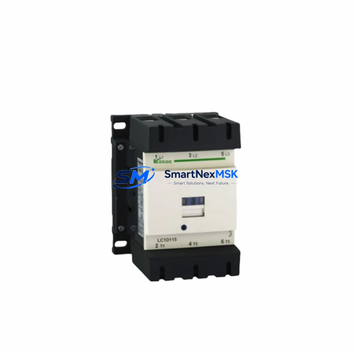
Schneider LC1D115M7C Retrofit-Ready Contactor for TeSys D Control Systems
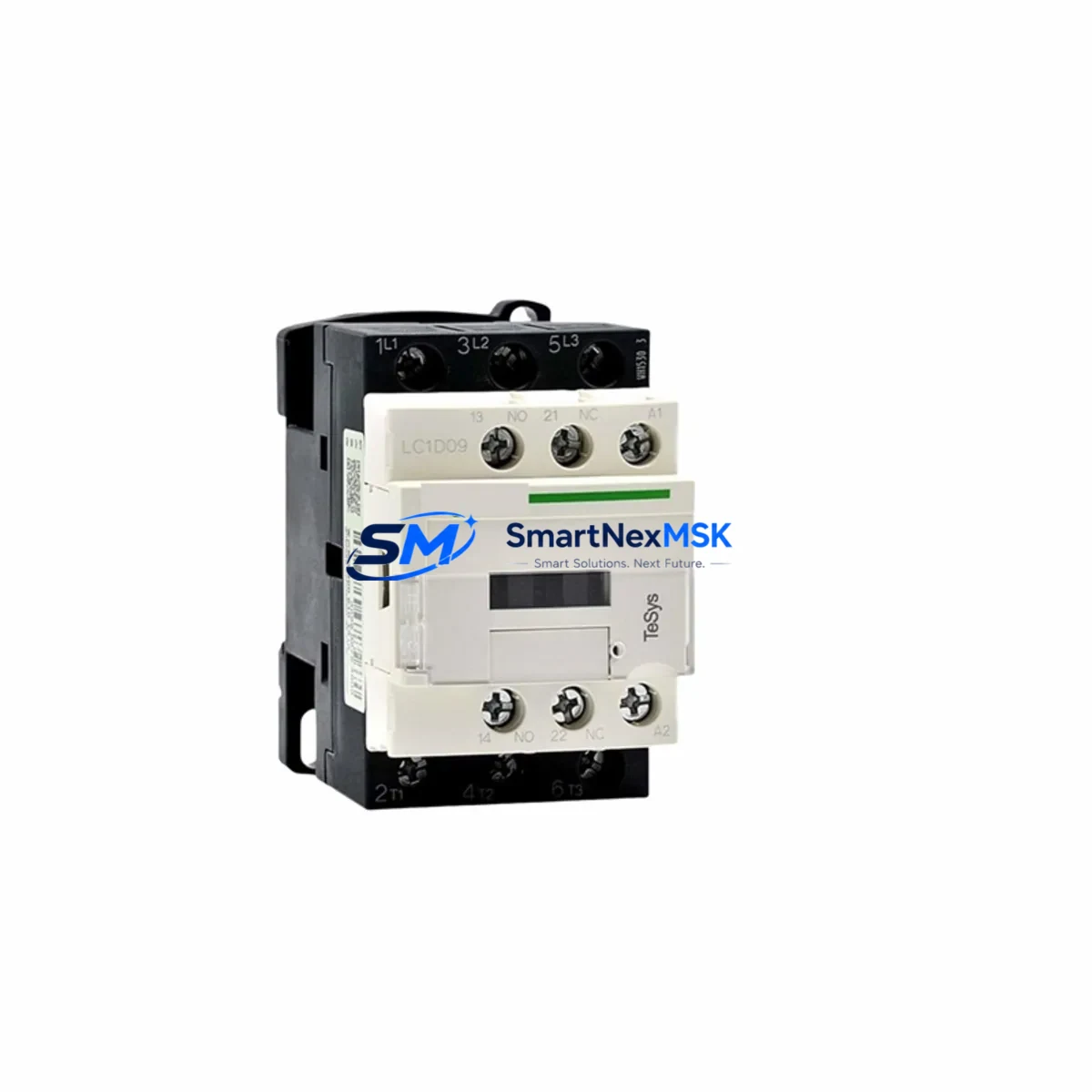
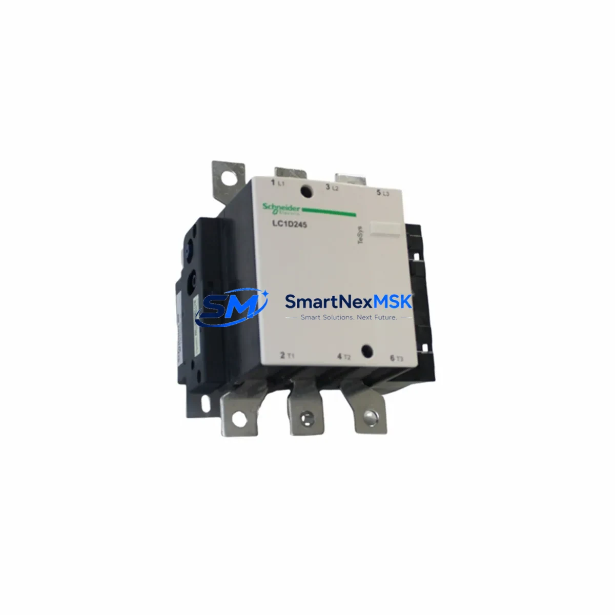
The Schneider Electric LC1D115M7C is a 115A, 3-pole AC contactor engineered for seamless compatibility with the TeSys D series control platform. Designed to serve as a direct retrofit replacement for aging or discontinued contactors in legacy motor control centers (MCCs), control cabinets, and industrial automation panels, the LC1D115M7C enables engineers and maintenance teams to modernize existing systems without redesigning the entire control architecture.
With a 220V AC (M7) coil voltage, this contactor integrates directly into standard IEC-compliant control circuits. Its compact DIN-rail and panel-mount footprint matches the original TeSys D envelope, allowing drop-in installation with minimal rewiring. Whether you are replacing a failed LC1D95M7C or stepping up capacity from a smaller frame, the LC1D115M7C delivers the current rating and mechanical endurance required for demanding industrial duty cycles.
Upgrade Compatibility Table
| Parameter | LC1D115M7C (This Unit) | Typical Legacy Replacement Target |
|---|---|---|
| Rated Current (AC-3) | 115A | 95A–115A (LC1D95 / LC1D115 series) |
| Coil Voltage | 220V AC (50/60Hz) | 220V AC — direct match |
| Poles | 3-pole main + auxiliary | 3-pole — direct match |
| Mounting | DIN rail / panel screw | Compatible with existing TeSys D rail positions |
| Auxiliary Contact | 1NO + 1NC (standard) | Expandable via LA1D auxiliary contact blocks |
| Communication Compatibility | Compatible with TeSys T motor management relay | Supports Modbus RTU / EtherNet/IP via gateway |
| Replacement Recommendation | Direct drop-in for LC1D95M7C, LC1D115M7C legacy units | Verify coil voltage and auxiliary wiring before swap |
| Commissioning Notes | Confirm overload relay (LRD) rating matches motor FLA | Re-verify setpoint after replacement |
| Warranty | 12 Months — Covered against manufacturing defects from date of shipment | |
Retrofit Planning for Existing Automation Systems
Successful retrofit of the LC1D115M7C into an existing control system requires a structured pre-installation review. Begin by auditing the control cabinet layout: confirm that the existing DIN rail spacing accommodates the TeSys D frame width and that adjacent components — including the LRD340 overload relay or LRD350 overload relay — are rated for the new 115A operating point. The overload relay must be re-selected or re-calibrated to match the full-load amperage (FLA) of the connected motor.
Next, inspect the control wiring to terminals A1 and A2 (coil supply). If the original installation used a LC1D95M7C or similar predecessor, the coil voltage wiring is typically a direct carry-over. However, if the legacy unit used a DC coil variant (e.g., BD or ED suffix), a coil voltage adapter or replacement control transformer may be required. Verify the control transformer secondary output and fuse rating before energizing.
For systems using a TeSys T LTM R motor management relay or a Tesys U starter-controller, confirm that the contactor’s auxiliary contact block (LA1DN11 or LA1DK11) is correctly wired to the motor management relay’s feedback input. This feedback loop is critical for remote trip confirmation and restart interlock logic in PLC-controlled systems.
In applications where the LC1D115M7C is integrated into a Modicon M340 or Modicon M580 PLC control system, verify that the digital output module — such as a BMX DDO 3202K discrete output card — is rated to drive the 220V AC coil directly or through an interposing relay. Review the PLC program for any hardcoded timer values associated with contactor pull-in delay, as mechanical response times may vary slightly between new and legacy units.
Where the retrofit involves a Pragma or Prisma distribution board housing the motor starter assembly, confirm that the busbar tap-off rating and the circuit breaker upstream (e.g., GV2ME or GV3ME motor circuit breaker) are coordinated with the 115A contactor. Coordination tables in the TeSys D catalog should be referenced to confirm Type 2 coordination compliance.
Finally, if the system includes a Magelis HMIGTO or HMISTO HMI panel with motor status screens, update the HMI tag database to reflect any I/O address changes resulting from the retrofit. Confirm that the motor run/fault status bits mapped from the PLC are still valid after the hardware swap.
Downtime Control During System Migration
Minimizing production downtime during a contactor retrofit requires advance preparation and a disciplined changeover sequence. Before the maintenance window opens, pre-wire the LC1D115M7C on a temporary mounting plate and pre-test coil continuity, auxiliary contact operation, and mechanical latch function using a portable 220V AC test source. This bench verification eliminates the most common causes of extended downtime — coil failure, incorrect auxiliary wiring, and terminal torque errors.
During the changeover, photograph the existing terminal wiring before disconnection. Label each conductor with its terminal designation (A1, A2, L1, L2, L3, T1, T2, T3, and auxiliary terminals). Disconnect the motor load terminals first, then the control wiring, and finally the coil supply. Install the LC1D115M7C, reconnect in reverse order, and torque all terminals to the manufacturer’s specification (typically 6–10 N·m for main power terminals on this frame size).
After reconnection, perform a no-load energization test: apply control power and verify coil pull-in, auxiliary contact state change, and release. Only then reconnect the motor load and perform a supervised test start. Monitor motor current on the first start cycle using a clamp meter to confirm the overload relay setpoint is appropriate. This structured sequence typically allows a complete contactor swap to be completed within a 30–60 minute planned maintenance window, preserving the original PLC program logic and HMI screen configurations without modification.
All units are pre-tested prior to shipment and backed by a 12-month warranty covering manufacturing defects from the date of delivery.
Retrofit Support FAQ
Q1: Is the LC1D115M7C a direct replacement for the LC1D95M7C?
The LC1D115M7C shares the same TeSys D frame and coil voltage (220V AC) as the LC1D95M7C, making it a compatible upgrade in most applications. The primary difference is the higher current rating (115A vs. 95A). Confirm that the upstream circuit breaker and overload relay are re-rated accordingly before installation.
Q2: Can this contactor be used with a Modicon PLC digital output module?
Yes. The 220V AC coil can be driven directly from a relay output module or through an interposing relay from a transistor output module. Verify the output module’s rated load current against the contactor coil inrush current (typically 5–10× the sealed current) to ensure reliable pull-in without output module damage.
Q3: What auxiliary contact blocks are compatible with this unit?
The LC1D115M7C accepts standard TeSys D series auxiliary contact blocks, including the LA1DN11 (1NO+1NC), LA1DK11 (2NO+2NC), and LA1DN22 (2NO+2NC) blocks. These mount directly to the front face of the contactor without tools and are compatible with the existing wiring in most TeSys D installations.
Q4: Does the unit come with a warranty, and what does it cover?
Yes. Every LC1D115M7C unit shipped from our stock is covered by a 12-month warranty from the date of shipment. The warranty covers manufacturing defects, coil failure, and contact welding under normal operating conditions. Units are pre-tested before dispatch. For warranty claims, contact our technical support team with the order reference and a description of the fault.
© 2026 SMARTNEXMSK. All rights reserved.
Original Source: https://smartnexmsk.com
Contact: [email protected] | +86 18259474341