
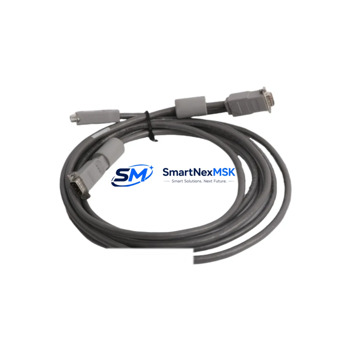
Siemens 16137-177 Retrofit-Ready Signal Module for TELEPERM Control Systems
The Siemens 16137-177 is a signal module originally designed for the TELEPERM M distributed control system — one of Siemens’ most widely deployed process automation platforms in the chemical, petrochemical, power generation, and water treatment industries. As TELEPERM M has reached end-of-life and spare parts become increasingly scarce, the 16137-177 has become a critical retrofit component for engineers tasked with extending the operational life of existing control infrastructure or executing a phased migration to modern platforms such as SIMATIC PCS 7 or SIMATIC S7-400.
SMARTNEXMSK maintains verified stock of the Siemens 16137-177 sourced from controlled supply chains, with each unit subject to pre-shipment functional testing. All units are covered by a 12-month warranty against manufacturing defects and operational failure under normal service conditions.
Upgrade Compatibility Table
| Parameter | Details |
|---|---|
| SKU / Part Number | 16137-177 |
| Brand / Manufacturer | Siemens AG |
| Series / Platform | TELEPERM M (TM) |
| Module Type | Signal Module (Analog/Digital I/O) |
| Backplane Interface | TELEPERM M subrack bus (compatible with AS 230 / AS 235 automation stations) |
| Installation | Subrack slot insertion — no tools required; observe ESD precautions |
| Power Supply Compatibility | 24 VDC via subrack backplane; verify PS 405 / PS 407 power supply capacity before installation |
| Communication Compatibility | TELEPERM M internal bus; compatible with CS 275 / SINEC H1 communication links |
| Direct Replacement For | Siemens 16137-177 (same SKU, OEM equivalent) |
| Migration Path | SIMATIC PCS 7 / S7-400 with ET 200M I/O adapter as intermediate step |
| Commissioning Notes | Verify module address via DIP switch; re-download function block parameters from CFC/SFC engineering tool |
| Warranty | 12 Months — covers functional failure under normal operating conditions |
Retrofit Planning for Existing Automation Systems
Replacing the 16137-177 in a live TELEPERM M installation requires careful pre-work to avoid unplanned downtime. Before pulling the module, engineers should document the current terminal wiring using the existing loop drawings and verify that the field signal cables — typically connected via the front connector of the subrack — are correctly labeled. The front connector on TELEPERM M signal modules is unpluggable, which simplifies hot-swap procedures in systems where redundancy is configured, but in single-channel configurations a controlled shutdown of the affected loop is strongly recommended.
Power budget verification is a mandatory step. The AS 230 or AS 235 automation station hosting the 16137-177 draws its 24 VDC supply from a dedicated PS 405 or PS 407 power supply module. Adding a replacement or additional signal module increases the total current draw on the subrack bus. Engineers should confirm that the installed power supply has sufficient headroom — typically at least 20% reserve — before inserting the new module. If the subrack is already near capacity, a PS 407 power supply upgrade may be required in parallel.
For sites planning a broader migration from TELEPERM M to SIMATIC PCS 7, the 16137-177 replacement is often part of a phased approach. In the first phase, the existing TELEPERM M subrack continues to operate while new SIMATIC S7-400 controllers are installed in parallel. The ET 200M distributed I/O station, connected via PROFIBUS DP, is commonly used as an intermediate I/O adapter, allowing field wiring to remain unchanged while the control logic is migrated to STEP 7 or the CFC engineering environment. During this transition, the IM 153-2 interface module within the ET 200M rack handles the PROFIBUS communication, and SM 331 / SM 332 analog I/O modules replicate the signal handling previously performed by the 16137-177.
HMI migration is another consideration. Existing TELEPERM M operator stations running WinCC OS or legacy COROS LS/B displays will need their process pictures updated to reflect the new tag structure once the S7-400 or PCS 7 controller takes over. The CP 443-1 communication processor handles Ethernet connectivity for the new controller, while the existing MPI/PROFIBUS network can be retained during the transition period to maintain communication with any remaining TELEPERM M nodes.
For sites that are not yet ready for a full platform migration, maintaining a stock of verified 16137-177 modules is the most cost-effective strategy. SMARTNEXMSK supplies this module with full traceability documentation, pre-shipment test reports, and ESD-safe packaging to ensure the unit arrives ready for immediate installation.
Downtime Control During System Migration
Minimizing unplanned downtime during a TELEPERM M signal module replacement begins with a structured pre-maintenance checklist. Before the maintenance window opens, the replacement 16137-177 should be bench-tested against a known-good reference configuration if a spare subrack is available. The module address — set via DIP switches on the module face — must be configured to match the slot assignment defined in the TELEPERM M system configuration database before insertion.
During the swap, the original function block parameters stored in the AS 230 / AS 235 automation station memory are typically retained, as they are held in battery-backed RAM. However, if the station has experienced a power loss or battery failure, a full parameter download from the engineering workstation will be required. Engineers should have the STEP M or CFC project files accessible and the programming cable — typically a serial or USB-to-serial adapter connected to the MPI port — ready before beginning the swap.
After module insertion and front connector re-engagement, the loop should be brought back online in manual mode first, with the field signal verified against the expected process value before switching back to automatic control. This approach protects the original program logic, prevents spurious control outputs, and maintains field control continuity throughout the replacement procedure. Total planned downtime for a single-module swap, when all preparation steps are completed in advance, is typically under 30 minutes.
Retrofit Support FAQ
Q1: Is the 16137-177 a direct drop-in replacement for the original Siemens module?
Yes. The 16137-177 supplied by SMARTNEXMSK is an OEM-equivalent unit with the same part number, form factor, backplane connector pinout, and electrical specification as the original Siemens production module. No wiring modifications or configuration changes are required beyond verifying the DIP switch address setting.
Q2: What commissioning steps are required after installing the replacement module?
After physical installation, verify the module address DIP switches match the slot assignment in the TELEPERM M configuration. Power up the subrack and confirm the module status LED indicates normal operation. Re-download function block parameters from the engineering workstation if the station memory has been cleared. Bring the affected loop online in manual mode, verify the signal value, then return to automatic control.
Q3: Can this module be used during a phased migration to SIMATIC PCS 7 or S7-400?
Yes. The 16137-177 can continue to operate in the existing TELEPERM M subrack while the new SIMATIC platform is commissioned in parallel. This phased approach allows field wiring and process interlocks to remain active throughout the migration, with cutover performed loop-by-loop to minimize risk and control downtime.
Q4: What does the 12-month warranty cover?
The 12-month warranty covers functional failure of the module under normal operating conditions, including backplane communication faults, signal processing errors, and power regulation failures attributable to the module itself. Each unit ships with a pre-shipment test report. Warranty claims are handled directly by SMARTNEXMSK with replacement dispatch within 5 business days of confirmed fault diagnosis.
© 2026 SMARTNEXMSK. All rights reserved.
Original Source: https://smartnexmsk.com
Contact: [email protected] | +86 18259474341



