
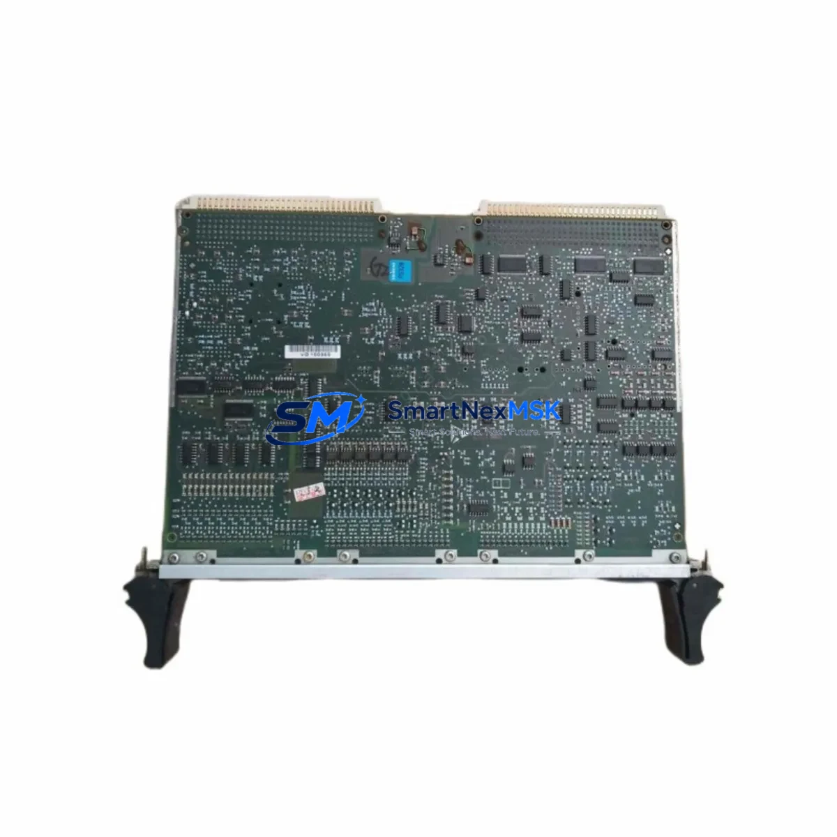
Siemens 16413-16-01 Retrofit-Ready Interface Module for S5 Control Systems
The Siemens 16413-16-01 is a proven interface module designed for the Simatic S5 series programmable logic controller platform — one of the most widely deployed industrial control architectures in manufacturing, process automation, and utility infrastructure. As the S5 series has reached end-of-life status, many facilities operating legacy S5-115U, S5-135U, and S5-155U systems are now facing the critical challenge of sourcing reliable replacement modules to sustain production continuity without committing to a full system overhaul. The 16413-16-01 addresses this need directly, serving as a drop-in interface solution that preserves existing backplane wiring, rack geometry, and program logic without requiring a complete controller migration.
For engineers managing aging control cabinets, the 16413-16-01 integrates seamlessly into the S5 subrack architecture. It occupies a standard S5 slot and communicates over the S5 backplane bus, maintaining compatibility with existing CPU modules such as the CPU 944, CPU 945, and CPU 948. When replacing a failed or end-of-life interface module, technicians should verify the slot address assignment and confirm that the replacement module’s DIP switch configuration matches the original unit before powering the rack. This step is critical to avoid address conflicts with adjacent I/O modules, communication processors, or function modules installed in the same rack.
Power budget verification is an essential pre-installation step. The S5 power supply modules — including the PS 951 and PS 955 — must have sufficient reserve capacity to support the 16413-16-01 alongside all other installed modules. Engineers should calculate the total current draw across the 5 VDC and 24 VDC rails before finalizing the retrofit plan. In cases where the existing power supply is operating near its rated capacity, upgrading to a higher-output PS module may be necessary to ensure stable operation after the interface module replacement.
Terminal wiring compatibility is another key consideration. The 16413-16-01 uses the standard S5 front connector system, which means existing field wiring can typically be transferred directly from the old module to the replacement unit without re-termination. However, technicians should inspect connector pins for corrosion or mechanical wear, particularly in installations that have been in service for more than a decade. Replacing the front connector itself is recommended if any pin damage is detected, as poor contact resistance at the terminal level can cause intermittent faults that are difficult to diagnose during commissioning.
Upgrade Compatibility Table
| Parameter | Details |
|---|---|
| SKU / Part Number | 16413-16-01 |
| Brand | Siemens |
| Compatible Series | Simatic S5 (S5-115U, S5-135U, S5-155U) |
| Module Type | Interface Module |
| Backplane Interface | S5 Subrack Bus |
| Installation | Standard S5 slot, front connector wiring |
| Communication Compatibility | S5 backplane bus; compatible with CP 523, CP 524, CP 525 communication processors |
| Replacement Recommendation | Direct replacement for failed or EOL 16413-16-01 units in S5 racks |
| Commissioning Notes | Verify DIP switch address, power budget, and front connector integrity before power-on |
| Warranty | 12-Month Warranty included |
Retrofit Planning for Existing Automation Systems
A successful retrofit of the 16413-16-01 into an existing S5 control system requires a structured approach that accounts for the full scope of the control architecture. Before removing the failed module, engineers should perform a full backup of the PLC program using a PG 702 or PG 740 programming device, or via a modern PC-based interface using Step 5 software. Retaining a verified program backup ensures that any accidental memory loss during the module swap can be recovered without extended downtime.
In systems where the S5 rack communicates with an HMI panel — such as a Siemens OP 17, OP 27, or TP 270 — the interface module replacement may temporarily interrupt the communication link between the CPU and the HMI. Operators should be informed in advance, and HMI screens should be placed in manual override or safe-state mode before the module is removed. After reinstallation, the communication link should be re-established and all HMI variable mappings verified against the original configuration to confirm that process values are displaying correctly.
For facilities that are using the S5 system in conjunction with distributed I/O via ET 200 remote stations connected over Profibus-DP, the interface module replacement should be coordinated with a review of the Profibus network configuration. The GSD file assignments and station addresses for each ET 200 node should be documented before the retrofit begins. After the 16413-16-01 is installed and the CPU is restarted, the Profibus master should be monitored for any station fault messages that could indicate address conflicts or communication timeouts introduced during the module change.
In control cabinets where the S5 rack shares enclosure space with a Siemens SIMOREG DC drive controller or a Micromaster frequency inverter, the retrofit plan should include a check of the analog and digital I/O wiring between the PLC and the drive system. Any I/O module — such as a 6ES5 482 digital output module or a 6ES5 464 analog input module — that interfaces with the drive should be tested for correct signal levels after the interface module is replaced and the system is returned to automatic mode.
Downtime Control During System Migration
Minimizing unplanned downtime is the primary operational concern when replacing a critical interface module in a live production environment. The recommended approach is to pre-stage the replacement 16413-16-01 unit in advance, with all DIP switch settings configured to match the original module before the maintenance window begins. This eliminates configuration time during the actual swap and reduces the total time the system is offline.
Where possible, the replacement should be scheduled during a planned maintenance window rather than performed as an emergency repair. This allows time for a controlled CPU stop, a verified program backup, a physical inspection of the rack and wiring, and a structured power-up sequence. After the new module is installed, the CPU should be started in STOP mode first, allowing the program to be verified before switching to RUN mode. This approach protects the original control logic and prevents unintended output activation during the commissioning phase.
For systems where continuous operation is required, a hot-standby or redundant CPU configuration — if present — should be used to maintain control during the module replacement. In non-redundant systems, coordinating the swap with the production schedule to coincide with a natural process break is the most effective strategy for limiting the impact on output. All field devices connected to the affected rack should be placed in a safe state before power is removed, and the restoration sequence should follow the site’s documented startup procedure to ensure a controlled return to automatic operation.
After the system is returned to service, a post-commissioning check should include verification of all I/O signals, confirmation of correct HMI display values, review of the CPU diagnostic buffer for any fault entries, and a functional test of all control loops associated with the replaced module. This structured verification process ensures that the retrofit is complete and that the system is operating correctly before the maintenance window is closed. All test results should be documented and retained as part of the site’s maintenance record.
Retrofit Support FAQ
Q: Is the 16413-16-01 a direct drop-in replacement for the original Siemens module?
A: Yes. The 16413-16-01 is a direct replacement for the original Siemens part of the same SKU. It uses the same S5 front connector, occupies the same rack slot, and communicates over the standard S5 backplane bus. No hardware modifications to the rack or wiring are required. DIP switch settings should be verified to match the original module configuration before installation.
Q: What commissioning steps are required after installing the replacement module?
A: After physical installation, verify the DIP switch address settings, confirm the power supply budget is within rated limits, and perform a controlled CPU start in STOP mode. Reload the program backup if required, verify all I/O signal states, and check the CPU diagnostic buffer for fault entries. For systems with HMI panels or Profibus-connected ET 200 stations, confirm that all communication links are re-established before switching the CPU to RUN mode.
Q: Can the 16413-16-01 be used in both S5-135U and S5-155U racks?
A: The 16413-16-01 is compatible with the standard S5 subrack architecture used across the S5-115U, S5-135U, and S5-155U platforms. Compatibility should be confirmed against the original system documentation and the module’s technical datasheet. If the original installation used a specific rack configuration or slot assignment, this should be replicated in the replacement installation.
Q: What warranty and testing does the replacement module include?
A: Every 16413-16-01 unit supplied by SMARTNEXMSK is covered by a 12-month warranty from the date of shipment. Each module undergoes functional testing prior to dispatch to verify correct operation. Units are shipped with appropriate anti-static packaging and documentation. In the event of a warranty claim, SMARTNEXMSK provides direct technical support and replacement coordination to minimize impact on production operations.
© 2026 SMARTNEXMSK. All rights reserved.
Original Source: https://smartnexmsk.com
Contact: [email protected] | +86 18259474341



