
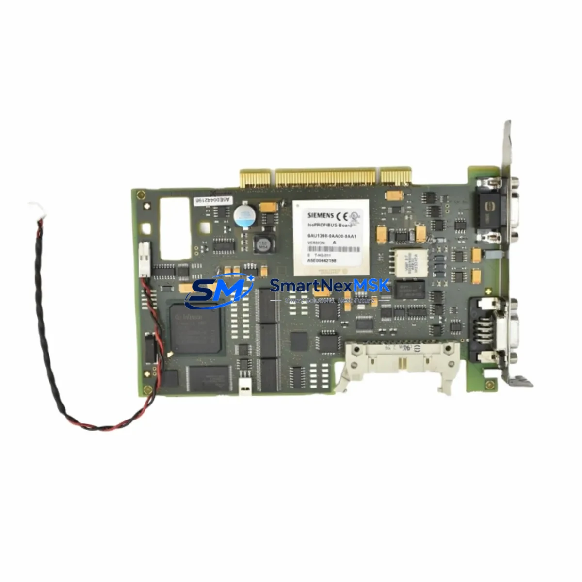
Siemens 6AU1390-0AA00-0AA1 Retrofit-Ready Servo Drive for SIMODRIVE Control Systems
The Siemens 6AU1390-0AA00-0AA1 (A5E00442198) is a servo drive control module engineered for the SIMODRIVE platform — one of Siemens’ most widely deployed motion control architectures in CNC machining centers, transfer lines, and high-precision manufacturing automation. As original SIMODRIVE hardware reaches end-of-life and spare parts become increasingly scarce, this module serves as a verified retrofit-ready replacement that preserves existing wiring topology, backplane interface assignments, and drive parameterization without requiring a full system redesign.
For engineers managing aging SIMODRIVE 611 or SIMODRIVE 611U drive cabinets, the 6AU1390-0AA00-0AA1 addresses the most critical challenge in legacy system modernization: maintaining axis control continuity while replacing discontinued control hardware. The module is compatible with the standard SIMODRIVE backplane rack and interfaces directly with the existing 611 power modules, eliminating the need to re-engineer the DC bus architecture or replace the infeed/regenerative unit.
Upgrade Compatibility Table
| Parameter | Details |
|---|---|
| Part Number | 6AU1390-0AA00-0AA1 |
| Reference Number | A5E00442198 |
| Brand | Siemens |
| Series | SIMODRIVE 611 / 611U |
| Module Function | Servo Drive Control Module |
| Backplane Interface | SIMODRIVE 611 standard rack — direct slot replacement |
| Communication Compatibility | PROFIBUS-DP, internal SIMODRIVE drive bus |
| Replacement Recommendation | Drop-in replacement for discontinued 6AU1390-0AA00-0AA1 variants; verify firmware revision before commissioning |
| Installation Requirement | Match slot address and axis assignment in SIMATIC S7 or SINUMERIK NCK parameter set |
| Commissioning Note | Re-upload drive parameters via STARTER or SIMOCOM U after module swap; verify encoder feedback signal integrity |
| Warranty | 12 Months — covers manufacturing defects and functional failure under normal operating conditions |
Retrofit Planning for Existing Automation Systems
A successful retrofit of the 6AU1390-0AA00-0AA1 begins well before the module arrives on-site. Engineers should first audit the existing SIMODRIVE 611 cabinet to document the current rack configuration, including the position of the infeed module, the 6SN1145 or 6SN1146 power supply unit, and each axis control module slot assignment. The 6AU1390-0AA00-0AA1 occupies a single slot in the standard SIMODRIVE backplane and draws its logic supply from the 24 VDC rail provided by the cabinet power supply — typically a 6EP1 series SITOP power supply unit. Confirm that the existing SITOP or equivalent 24 VDC supply has sufficient current headroom before installation.
Terminal wiring on the SIMODRIVE 611 control module connector follows the standard X121/X131 interface pinout. Before disconnecting the existing module, photograph or document all terminal assignments, particularly the enable signals, speed setpoint inputs (analog ±10 V or digital via PROFIBUS-DP), and the motor encoder feedback connector — typically a 15-pin Sub-D for resolver or TTL incremental encoder. The 6AU1390-0AA00-0AA1 uses the same connector layout, so wiring transfers directly without modification in most retrofit scenarios.
For systems where the SINUMERIK 840D sl or 840Di sl CNC controller manages axis motion, the drive module address must be re-confirmed in the NCK machine data after replacement. The SIMODRIVE drive bus topology — which links the NCU (Numerical Control Unit) to each axis module via the internal drive bus ribbon cable — must remain intact. Inspect the ribbon cable and backplane bus connectors for wear before re-energizing the cabinet. In multi-axis cabinets, also verify that the 6SN1118 or 6SN1123 axis control boards in adjacent slots are not affected by the swap.
Where the control system communicates over PROFIBUS-DP, confirm that the GSD file and DP slave address assigned to the drive axis remain consistent with the replacement module’s firmware. If the system uses a SIMATIC S7-300 or S7-400 PLC as the motion coordinator — common in transfer line and gantry applications — re-download the hardware configuration from STEP 7 or TIA Portal after the module swap to re-establish the DP communication link. For systems migrating from older SIMODRIVE 611A analog drives to the 611U digital variant, a PROFIBUS-DP communication board (6SN1114 series) may need to be added to the new module to support the digital setpoint interface.
I/O expansion requirements should also be assessed during retrofit planning. If the existing control cabinet includes a SIMODRIVE 611 terminal module (6SN1112 series) for additional digital I/O — such as axis-specific enable, fault reset, or position switch inputs — verify that these terminal modules remain compatible with the replacement control module’s firmware version. In some retrofit scenarios, engineers also replace the operator panel interface, upgrading from an older OP7 or OP17 HMI panel to a modern TP700 Comfort or KTP700 Basic panel, which requires updating the HMI project in WinCC Flexible or TIA Portal WinCC to match the new screen layout and variable mapping.
Downtime Control During System Migration
Minimizing unplanned downtime during a SIMODRIVE control module replacement requires a structured pre-swap preparation protocol. Before taking the machine offline, use STARTER commissioning software or SIMOCOM U to perform a full parameter backup of the existing drive module. Save the parameter file (.upl or .xml format) to a secure location — this file contains all motor data, encoder configuration, speed/torque limits, and closed-loop control gains that define the axis behavior. If the original module has failed and cannot be read, the parameter set can often be reconstructed from the motor nameplate data and the machine’s original commissioning documentation.
Plan the physical swap during a scheduled maintenance window. Power down the SIMODRIVE cabinet following the correct sequence: disable the NC program, deactivate the axis enables, switch off the main contactor, and discharge the DC bus capacitors before opening the cabinet door. The 6AU1390-0AA00-0AA1 is secured by a front-panel locking lever and slides out of the backplane slot — no tools are required for module extraction. After inserting the replacement module, restore power in reverse sequence and verify that the drive bus communication is re-established before attempting axis motion.
Once the module is installed and powered, re-download the saved parameter set via STARTER or SIMOCOM U. Perform a static motor identification run if the motor data has changed, then execute a speed controller optimization to re-tune the current and speed control loops. Verify encoder feedback by jogging the axis at low speed and confirming position feedback consistency in the drive diagnostic screen. Before returning the machine to production, run a full axis function test including end-of-travel limit switch verification, following error monitoring, and spindle orientation if applicable. This structured commissioning sequence typically allows a trained engineer to complete the swap and return the machine to production within two to four hours, keeping unplanned downtime to a minimum.
Retrofit Support FAQ
Q: Is the 6AU1390-0AA00-0AA1 a direct drop-in replacement for the original SIMODRIVE module?
A: In most SIMODRIVE 611 cabinet configurations, yes. The module uses the same backplane slot, connector pinout, and drive bus interface as the original. However, you should verify the firmware revision and confirm that the motor encoder type (resolver, TTL, or EnDat) matches the encoder interface supported by the replacement module before installation.
Q: Do I need to re-wire the terminal block when replacing the control module?
A: No re-wiring is required in standard retrofit scenarios. The X121/X131 terminal connector and the encoder Sub-D connector transfer directly from the old module to the new one. Document all wiring before removal as a precaution, and inspect connector pins for corrosion or mechanical damage during the swap.
Q: How do I restore the drive parameters after installing the replacement module?
A: Use Siemens STARTER software or SIMOCOM U to re-download the parameter backup file (.upl or .xml) saved from the original module. If no backup exists, parameters can be reconstructed from the motor nameplate, machine documentation, and Siemens drive configuration guidelines. A speed controller optimization run is recommended after parameter restore to re-tune the control loops for the specific motor and mechanical load.
Q: What warranty coverage is included with this module?
A: All modules supplied by SMARTNEXMSK include a 12-month warranty covering manufacturing defects and functional failure under normal operating conditions. Each unit undergoes pre-shipment functional testing to verify drive bus communication, control output integrity, and power supply compatibility before dispatch. Contact [email protected] for warranty claims or technical support.
© 2026 SMARTNEXMSK. All rights reserved.
Original Source: https://smartnexmsk.com
Contact: [email protected] | +86 18259474341



