
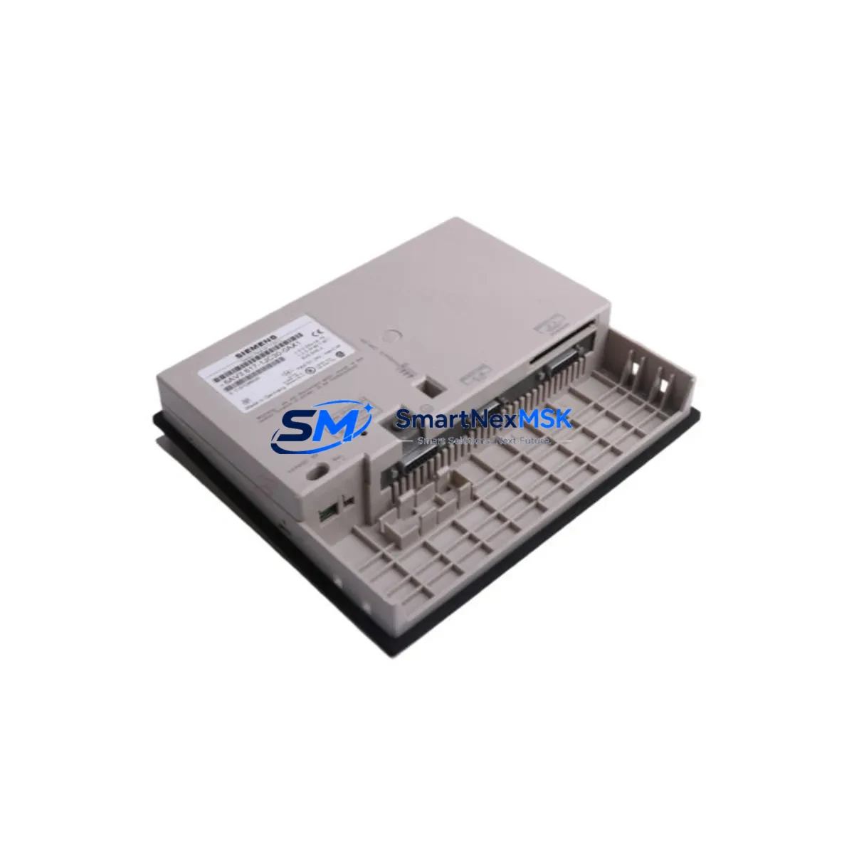
Siemens 6AV3617-1JC30-0AX1 Retrofit-Ready HMI for SIMATIC OP17 Control Systems
The Siemens 6AV3617-1JC30-0AX1 is a SIMATIC OP17 operator panel designed for seamless integration into legacy S7-300 and S7-400 control architectures. As production lines age and original OP17 units reach end-of-life, this unit serves as a verified retrofit replacement that preserves existing MPI communication links, terminal wiring layouts, and HMI screen configurations without requiring a full system redesign. For facilities managing aging SIMATIC control cabinets, the 6AV3617-1JC30-0AX1 offers a controlled, low-risk upgrade path that minimizes engineering rework and unplanned downtime.
Industrial sites running SIMATIC S7-300 CPUs — such as the CPU 315-2 DP or CPU 317-2 PN/DP — frequently encounter obsolescence challenges with their operator interface layer. The 6AV3617-1JC30-0AX1 addresses this directly: it maintains the same 9-pin MPI port pinout as the original OP17, supports the same ProTool configuration files used in legacy projects, and fits the standard panel cutout dimensions, eliminating the need for cabinet rework. Engineers can retain their existing STEP 7 project structure and HMI variable tables, reducing commissioning time significantly.
Before installation, retrofit planners should verify several critical parameters. First, confirm the 24 VDC power supply capacity at the control cabinet — the 6AV3617-1JC30-0AX1 draws approximately 200 mA, and shared rails powering other modules such as the SM 321 digital input module or SM 322 digital output module must have sufficient headroom. Second, inspect the existing MPI cable routing and confirm the network address assigned to the original OP17 is available and not duplicated on the MPI segment. Third, review the ProTool project file version to ensure compatibility with the replacement unit’s firmware baseline.
Terminal wiring on the 6AV3617-1JC30-0AX1 follows the standard SIMATIC OP17 connector layout. The 9-pin Sub-D MPI connector on the rear panel is pin-compatible with existing MPI cables used across the S7-300 rack. If the control cabinet also houses a CP 342-5 PROFIBUS communication processor or an IM 360 interface module for rack expansion, these components remain unaffected by the HMI swap and do not require reconfiguration. The backplane bus of the S7-300 rack continues to operate normally during the HMI replacement procedure.
For sites migrating from older SIMATIC S5 architectures to S7-based systems, the 6AV3617-1JC30-0AX1 can serve as the operator interface layer in the new S7 environment while legacy S5 equipment is phased out. In such scenarios, the MPI network may also carry traffic from a PG/PC programming cable connected via a PC Adapter USB, allowing engineers to monitor and adjust the HMI configuration live during the transition period without interrupting production.
Commissioning the 6AV3617-1JC30-0AX1 follows a structured sequence: power down the control cabinet, remove the original OP17 unit, install the replacement in the panel cutout, reconnect the MPI cable and 24 VDC supply, power up, and verify communication with the S7 CPU using STEP 7 or TIA Portal in legacy mode. HMI screen navigation, alarm messages, and process variable displays should be validated against the original ProTool project to confirm full functional equivalence. If the site uses a SIMATIC S7-300 with a CP 343-1 Ethernet module for supervisory SCADA connectivity, that communication path is independent of the HMI MPI link and remains active throughout the replacement process.
All units supplied by SMARTNEXMSK are subject to pre-shipment functional testing, including power-on verification, display integrity check, keypad response validation, and MPI port continuity test. Each 6AV3617-1JC30-0AX1 ships with a 12-month warranty covering manufacturing defects and functional failures under normal operating conditions. Inventory is maintained in stock for fast dispatch to support urgent maintenance and unplanned breakdown scenarios.
Upgrade Compatibility Table
| Parameter | Original OP17 (6AV3617-1JC20-0AX1) | Replacement 6AV3617-1JC30-0AX1 |
|---|---|---|
| Communication Interface | MPI (9-pin Sub-D) | MPI (9-pin Sub-D) — Pin-compatible |
| Supply Voltage | 24 VDC | 24 VDC — Direct replacement |
| Panel Cutout | Standard OP17 cutout | Identical — No cabinet modification required |
| Configuration Tool | ProTool v6.x | ProTool v6.x compatible — Existing project reusable |
| Compatible CPUs | S7-300, S7-400 via MPI | S7-300, S7-400 via MPI — No CPU change required |
| Installation Type | Panel mount | Panel mount — Same mounting hardware |
| Commissioning Requirement | ProTool download via MPI | ProTool download via MPI or PC Adapter USB |
| Warranty | N/A (discontinued) | 12-Month Warranty — Functional guarantee |
Retrofit Planning for Existing Automation Systems
A successful retrofit begins with a complete audit of the control cabinet. For systems built around the SIMATIC S7-300 platform, this typically means documenting the CPU model, the rack configuration including any SM 331 analog input modules or SM 332 analog output modules, the MPI network topology, and the existing HMI project files stored in the ProTool database. The 6AV3617-1JC30-0AX1 slots directly into this environment without requiring changes to the CPU program, the I/O module addressing, or the PROFIBUS DP network if one is present alongside the MPI segment.
Power budget verification is a mandatory step. Control cabinets housing multiple S7-300 modules — including the PS 307 power supply module, SM 321 and SM 322 I/O modules, and CP 342-5 communication processors — must be assessed to confirm the 24 VDC rail can support the additional HMI load. In most standard S7-300 configurations, the PS 307 5A or 10A power supply provides sufficient capacity, but aging power supplies with degraded output regulation should be tested under load before the retrofit is finalized.
MPI network address assignment must be confirmed before powering up the replacement HMI. The 6AV3617-1JC30-0AX1 must be assigned the same MPI node address as the original OP17 to ensure the S7 CPU’s communication configuration requires no modification. This address is set via the HMI’s startup menu and should be documented in the retrofit work order. If the MPI segment also carries traffic from a PG/PC running STEP 7 via a PC Adapter USB, the programming connection should be temporarily disconnected during HMI address configuration to avoid network conflicts.
For facilities managing multiple control cabinets with identical OP17 installations — common in batch processing, conveyor systems, and packaging lines — the 6AV3617-1JC30-0AX1 can be pre-configured and tested in a workshop environment before deployment to the production floor. This approach, combined with a pre-loaded ProTool project, reduces on-site commissioning time to under 30 minutes per panel in most cases.
Downtime Control During System Migration
Minimizing production interruption during an HMI replacement requires a structured change management approach. The recommended procedure for replacing an OP17 with the 6AV3617-1JC30-0AX1 is to schedule the swap during a planned maintenance window, pre-load the ProTool project onto the replacement unit in the workshop, and prepare all required tools — including the MPI cable, PC Adapter USB, and a laptop with STEP 7 or ProTool installed — before entering the production area.
The S7-300 CPU continues to execute its control program independently of the HMI during the swap. Process control is maintained through the CPU’s own program logic and the connected I/O modules. Operators should be informed that HMI visibility will be temporarily unavailable during the swap, but the controlled process — whether a conveyor, a pump station, or a packaging line — will continue to run under automatic control. If the process requires operator intervention during the window, a temporary manual override procedure should be documented and communicated before work begins.
After physical installation, the commissioning sequence should include: MPI communication verification using STEP 7’s accessible nodes function, HMI screen navigation test covering all process pages and alarm screens, and a functional check of all operator inputs including setpoint entry and mode selection. Total elapsed time from cabinet opening to verified commissioning is typically 20–45 minutes for a direct OP17 replacement using a pre-configured 6AV3617-1JC30-0AX1 unit. This controlled approach protects the original program logic, preserves field control continuity, and eliminates the risk of configuration errors introduced by rushed on-site programming.
Retrofit Support FAQ
Q: Is the 6AV3617-1JC30-0AX1 a direct drop-in replacement for the original SIMATIC OP17?
A: Yes. The 6AV3617-1JC30-0AX1 is mechanically and electrically compatible with the original OP17 installation. It uses the same panel cutout dimensions, the same 9-pin MPI connector, and the same 24 VDC supply. Existing ProTool project files can be downloaded directly to the replacement unit without modification in most cases.
Q: Do I need to modify my S7-300 CPU program after installing the replacement HMI?
A: No. The S7-300 CPU program does not require modification. The HMI communicates with the CPU via MPI using the same variable addresses and data blocks defined in the original ProTool project. As long as the MPI node address on the replacement unit matches the original, the CPU recognizes it as the same device.
Q: What pre-shipment testing is performed on each unit?
A: Each 6AV3617-1JC30-0AX1 undergoes power-on verification, display and backlight integrity check, full keypad response test, and MPI port continuity verification before dispatch. Units that do not pass all test criteria are not shipped. A 12-month warranty covering manufacturing defects and functional failures is included with every unit.
Q: What should I verify regarding wiring before installing the replacement unit?
A: Confirm the 24 VDC supply polarity and voltage level at the HMI terminal block, inspect the MPI cable for continuity and correct shielding, verify the MPI node address is not duplicated on the network segment, and confirm the panel cutout dimensions match the OP17 standard before mounting. These checks prevent the most common commissioning issues and ensure a clean first-power-up experience.
© 2026 SMARTNEXMSK. All rights reserved.
Original Source: https://smartnexmsk.com
Contact: [email protected] | +86 18259474341



