
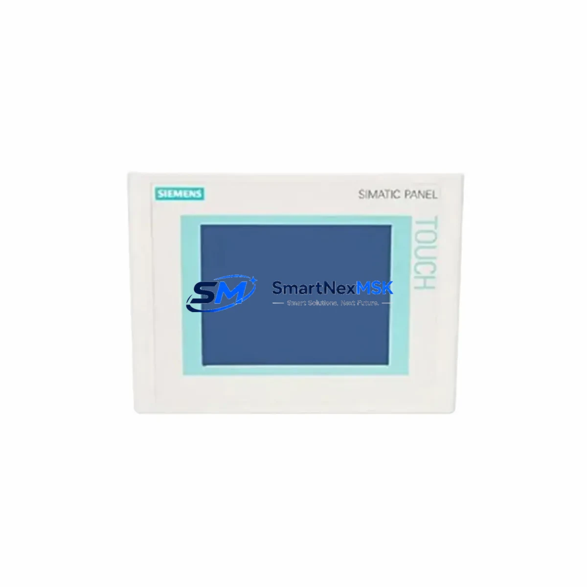
Siemens 6AV6642-0AA11-0AX1 Retrofit-Ready HMI for SIMATIC TP177A Control Systems
The Siemens 6AV6642-0AA11-0AX1 is a 5.7-inch color touch panel from the SIMATIC TP177A series, engineered for seamless integration into legacy and modernized industrial control environments. As production lines built around the SIMATIC S7-200, S7-300, and S7-400 controller families continue to operate well beyond their original design cycles, the demand for verified, retrofit-ready HMI replacements has grown significantly. This unit addresses that demand directly — offering a drop-in compatible upgrade path for facilities managing aging visualization infrastructure without the cost or disruption of a full system overhaul.
Whether your facility is replacing a failed panel, upgrading a control cabinet, or migrating from an obsolete SIMATIC OP77A or TP170A operator panel, the 6AV6642-0AA11-0AX1 provides the interface compatibility, communication protocol support, and physical form factor required for a controlled, low-risk transition. The panel supports MPI, PROFIBUS DP, and RS-422/485 communication links, making it directly compatible with the majority of legacy S7 controller backplanes and distributed I/O configurations still in active service.
Upgrade Compatibility Table
| Parameter | Details |
|---|---|
| SKU / Part Number | 6AV6 642-0AA11-0AX1 |
| Series | SIMATIC TP177A |
| Display | 5.7″ STN Color Touch Panel, 320×240 px |
| Communication Interfaces | MPI, PROFIBUS DP, RS-422/485 |
| Compatible Controllers | SIMATIC S7-200, S7-300, S7-400, S7-1200 (via adapter) |
| Replaces / Upgrades From | SIMATIC TP170A, OP77A, TP177 (non-color), OP177A |
| Panel Cutout Dimensions | 197 mm × 141 mm (standard TP177A cutout) |
| Power Supply | 24 V DC, 4.5 W typical |
| Mounting | Panel flush-mount, IP65 front protection |
| Programming Software | WinCC flexible 2008 SP3 or higher |
| Retrofit Recommendation | Direct replacement for TP170A / OP77A with project migration via WinCC flexible |
| Commissioning Notes | Verify MPI address, baud rate, and DB block mapping before power-on |
| Warranty | 12 Months — covers hardware defects under normal operating conditions |
Retrofit Planning for Existing Automation Systems
Successful integration of the 6AV6642-0AA11-0AX1 into an existing control system begins well before the panel arrives on-site. Engineers responsible for the retrofit should start by auditing the current control cabinet layout, confirming available 24 V DC power capacity from the existing SITOP PSU100S or equivalent power supply module, and verifying that the panel cutout dimensions match the TP177A standard. In most legacy installations, the cutout originally designed for a SIMATIC TP170A or OP77A will accept the TP177A without modification.
Communication wiring is the next critical checkpoint. The 6AV6642-0AA11-0AX1 connects to the S7-300 or S7-400 CPU via the MPI/PROFIBUS port using a standard 9-pin Sub-D connector. If the existing installation uses a PROFIBUS DP network with a CP 342-5 or CP 343-5 communications processor, the HMI can be integrated as a PROFIBUS slave without rewiring the field bus segment. For installations running RS-485 point-to-point links to a SIMATIC S7-200 CPU 224 or CPU 226, the panel’s built-in RS-422/485 port provides direct connectivity using the existing cable infrastructure.
Before removing the old panel, document the current MPI node address and baud rate settings — typically stored in the HMI project or on a label inside the cabinet door. The replacement 6AV6642-0AA11-0AX1 must be configured with the same MPI address to avoid address conflicts on the network, particularly in multi-panel installations where a SIMATIC OP177B or a second TP177A may share the same MPI segment. After physical installation, confirm that the SIMATIC S7 CPU’s MPI port recognizes the new HMI node using STEP 7 or TIA Portal’s accessible nodes scan before transferring the project.
Project migration from a legacy TP170A or OP77A is handled through WinCC flexible 2008. The migration wizard converts screen layouts, tag connections, and alarm configurations automatically, though engineers should manually verify any screens that reference system tags tied to the CPU’s DB blocks, particularly DB1 and DB2 structures commonly used in older S7-300 programs. HMI screen layouts referencing SIMATIC S7 data blocks, timer values, or counter outputs should be validated against the current PLC program in STEP 7 to confirm tag address mapping remains consistent after migration.
For installations that include a SIMATIC ET 200S distributed I/O station or a CP 343-1 Ethernet module on the same rack, no changes to the I/O configuration are required — the HMI retrofit is transparent to the PROFIBUS DP master and does not affect the I/O update cycle. Similarly, if the control system includes a SIMATIC S7-400 with a UR2 rack and multiple SM 321 digital input or SM 322 digital output modules, the HMI replacement has no impact on the rack’s backplane communication or module addressing.
Downtime Control During System Migration
Minimizing production downtime during an HMI retrofit requires a structured pre-commissioning approach. Before scheduling the physical swap, prepare a complete backup of the existing HMI project using WinCC flexible’s project archive function, and store a copy of the current STEP 7 or TIA Portal program on a secure engineering workstation. This ensures that if any issue arises during commissioning, the original configuration can be restored within minutes rather than hours.
The physical panel swap itself — disconnecting the old unit, installing the 6AV6642-0AA11-0AX1, and reconnecting power and communication cables — typically takes under 30 minutes for a trained technician familiar with the cabinet layout. The majority of retrofit downtime is consumed by project transfer and initial commissioning: loading the migrated WinCC flexible project via the panel’s USB port or MPI/PROFIBUS download interface, verifying screen navigation, confirming alarm acknowledgment behavior, and testing all operator inputs against live PLC outputs.
To further reduce risk, consider staging the retrofit during a planned maintenance window and pre-loading the HMI project onto the replacement panel in the workshop before it reaches the production floor. A pre-tested, pre-configured panel reduces on-site commissioning time to a final connectivity check and functional verification, protecting the original program logic and maintaining field control continuity throughout the transition. All units supplied by SMARTNEXMSK are pre-tested prior to shipment and covered by a 12-month warranty against hardware defects.
Retrofit Support FAQ
Q: Is the 6AV6642-0AA11-0AX1 a direct drop-in replacement for the SIMATIC TP170A?
A: Yes, in most installations. The panel cutout dimensions are compatible, and the MPI/PROFIBUS communication interface is identical. A project migration step in WinCC flexible is required to convert the existing TP170A project to the TP177A format, but no hardware modifications to the control cabinet or field wiring are typically needed.
Q: What programming software and cable are required for commissioning?
A: WinCC flexible 2008 SP3 or higher is required for project editing and transfer. The project can be downloaded to the panel via USB using a standard USB-A to USB-Mini-B cable, or via MPI/PROFIBUS using a PC Adapter USB A2 or SIMATIC NET CP 5711 adapter. Ensure the PC’s MPI baud rate matches the panel configuration before initiating the download.
Q: How do I verify communication compatibility with my existing S7-300 CPU before installation?
A: Use STEP 7’s “Accessible Nodes” function with the PC adapter connected to the MPI bus. Confirm the CPU is visible and note the active MPI addresses in use. Configure the replacement 6AV6642-0AA11-0AX1 with an unused MPI address (default is 1 for HMI panels) and set the baud rate to match the existing network — typically 187.5 kbps for MPI or 1.5 Mbps for PROFIBUS DP.
Q: What does the 12-month warranty cover, and what is the return process?
A: The 12-month warranty covers hardware defects arising under normal operating conditions, including display failures, communication port faults, and power supply issues. It does not cover damage resulting from incorrect wiring, overvoltage, or physical impact. To initiate a warranty claim, contact SMARTNEXMSK with the order reference and a description of the fault. Replacement or repair is arranged within 5 business days of fault confirmation.
© 2026 SMARTNEXMSK. All rights reserved.
Original Source: https://smartnexmsk.com
Contact: [email protected] | +86 18259474341



