
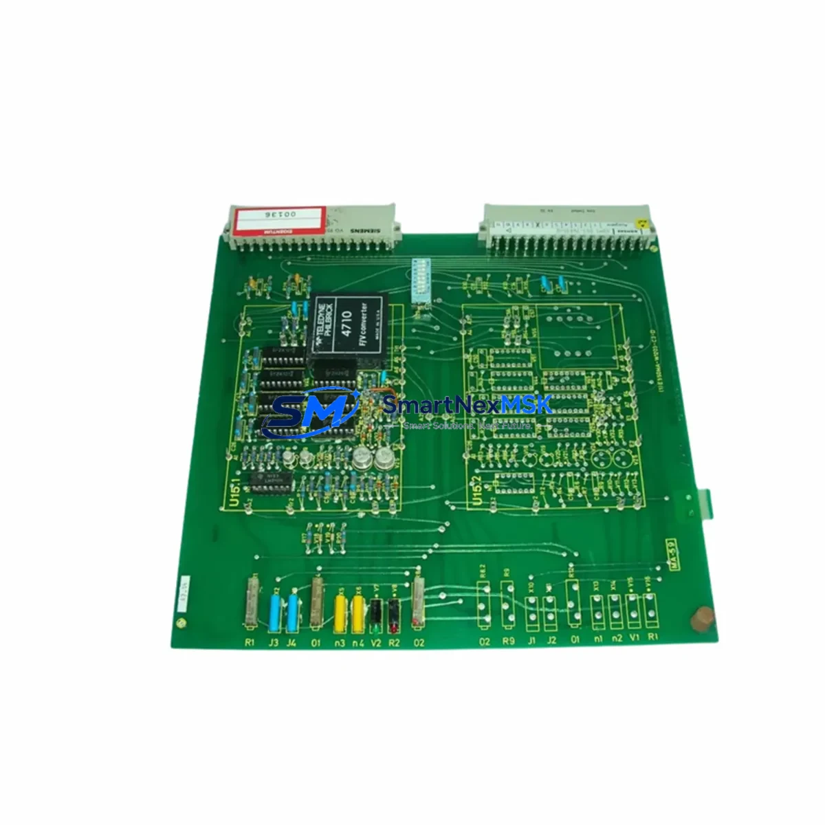
Siemens 6DM1001-7WA14-0 Retrofit-Ready Modulpac for SIMATIC S5 Control Systems: Seamless Legacy Upgrade & Compatibility Migration
The Siemens 6DM1001-7WA14-0 is a Modulpac interface module originally designed for the SIMATIC S5 programmable controller platform. As production lines built around the S5-115U, S5-135U, and S5-155U series approach end-of-life, procurement teams and automation engineers increasingly rely on verified replacement stock to sustain operations without committing to a full platform migration. This unit serves as a direct retrofit candidate for facilities that need to maintain existing rack architecture, preserve validated PLC programs, and avoid extended downtime during the transition period.
Whether you are replacing a failed module in a running production cell, building a spare-parts buffer for a legacy control cabinet, or executing a phased upgrade from SIMATIC S5 to SIMATIC S7-300 or S7-400, the 6DM1001-7WA14-0 provides a reliable, tested starting point. Each unit shipped from our inventory undergoes functional verification prior to dispatch and is covered by a 12-month warranty against manufacturing defects and operational failure.
Upgrade Compatibility Table
| Parameter | 6DM1001-7WA14-0 (This Unit) | Retrofit Notes |
|---|---|---|
| Platform Compatibility | SIMATIC S5 (S5-115U / S5-135U / S5-155U) | Verify rack slot assignment and backplane bus version before installation |
| Backplane Interface | S5 parallel backplane bus | Not compatible with S7 backplane; adapter required for S7 migration |
| Communication Protocol | SINEC H1 / Profibus DP (configuration-dependent) | Confirm existing network topology; CP 5431 FMS/DP or CP 5412 A2 may be present in the same rack |
| Terminal Wiring | Standard S5 front connector (40-pin) | Retain original wiring harness; verify terminal labeling against original I/O list |
| Power Supply Requirement | 24 V DC via rack power bus | Confirm PS 951 or PS 955 power supply capacity before adding modules to rack |
| Module Address Setting | DIP switch / slot-based addressing | Match address settings to original module configuration; document before removal |
| Program Compatibility | STEP 5 (S5 instruction set) | Programs remain valid; no recompilation required for like-for-like replacement |
| HMI Interface | Compatible with OP5, OP7, OP17, and TD series panels via MPI/PPI | Verify HMI screen variable addresses if DB structure has changed |
| Installation Format | S5 subrack (UR1 / UR2 / CR2) | Module occupies one slot; confirm available slot count in target rack |
| Replacement Path | Direct S5 replacement or S5→S7 migration with interface adapter | For S7 migration, consider IM 360 / IM 361 expansion interface modules |
| Warranty | 12-Month Warranty — covers functional failure under normal operating conditions | |
Retrofit Planning for Existing Automation Systems
Successful integration of the 6DM1001-7WA14-0 into an existing control system begins with a thorough audit of the target cabinet. Engineers should document the current rack layout, including the positions of the CPU 944B or CPU 945 processor module, any installed digital input modules such as the 6ES5 430-4UA12 or 6ES5 431-4UA12, analog output modules like the 6ES5 470-4UA12, and communication processors including the CP 5431 FMS/DP. This documentation forms the baseline for the replacement plan and prevents address conflicts during commissioning.
Power budget verification is a critical pre-installation step. The PS 951 and PS 955 power supply modules used in S5 racks have defined current limits per bus segment. Adding or replacing a Modulpac interface module changes the load profile, and exceeding the rated current will cause intermittent faults or prevent the CPU from entering RUN mode. Calculate the total current draw of all installed modules before proceeding.
Terminal wiring on S5 systems uses the standard 40-pin front connector. When removing the failed module, photograph the wiring layout and cross-reference it against the original I/O list before disconnecting any conductors. The replacement 6DM1001-7WA14-0 uses the same connector format, so the existing wiring harness can be transferred directly without modification in most cases. If the installation involves a UR2 expansion rack connected via IM 360 and IM 361 interface modules, verify that the expansion bus cable is seated correctly and that the rack address switches are set to match the original configuration.
For facilities planning a phased migration toward SIMATIC S7-300, the 6DM1001-7WA14-0 can serve as a bridge module during the transition period. The S7-300 platform uses a different backplane architecture and ET 200M distributed I/O stations connected via Profibus DP, but the S5 rack can remain operational in parallel while the new S7 system is commissioned on a separate segment. Communication between the two platforms during the transition can be managed through a CP 343-5 communication processor on the S7 side and the existing CP 5431 on the S5 side, allowing data exchange without interrupting production.
HMI panels connected to the S5 system, including OP5, OP7, OP17, and TD200 text displays, communicate via the MPI interface on the CPU. If the replacement module changes the DB structure or variable addresses, HMI screen configurations must be updated in ProTool or WinCC flexible before the new module is brought online. Failure to synchronize HMI variable addresses is a common cause of post-replacement alarm floods and operator interface failures.
Programming cables such as the PC Adapter USB A2 or the older 9-pin MPI cable are required for online diagnostics and program upload/download during commissioning. Ensure the engineering station running STEP 5 or STEP 7 is available on-site before the replacement window begins.
Downtime Control During System Migration
Minimizing unplanned downtime during a module replacement or system migration requires preparation that begins well before the maintenance window. The following approach has been validated across multiple S5 retrofit projects in process control, discrete manufacturing, and utilities environments.
Step 1 — Pre-replacement backup: Upload the complete STEP 5 program from the CPU to the engineering station using the programming cable. Save the program blocks (OBs, FBs, DBs, and SBs), system data, and I/O configuration to a secure location. This backup is the recovery baseline if the replacement does not proceed as expected.
Step 2 — Module address documentation: Record the DIP switch settings on the existing 6DM1001-7WA14-0 before removal. Photograph the front panel, the slot position in the rack, and the wiring harness. Set the replacement module to identical address settings before installation.
Step 3 — Hot-swap assessment: The S5 platform does not support hot-swapping of Modulpac interface modules. The CPU must be placed in STOP mode before the module is removed. Coordinate with the production team to schedule the STOP window during a planned break or shift changeover to minimize impact on output.
Step 4 — Post-installation verification: After installing the 6DM1001-7WA14-0, power up the rack and observe the CPU status LEDs. The BASP (command output disable) LED should extinguish and the RUN LED should illuminate within the normal startup sequence. Use the programming cable to perform an online comparison between the uploaded backup and the program currently in the CPU to confirm program integrity.
Step 5 — Communication link verification: If the module interfaces with a Profibus DP network or SINEC H1 segment, verify that all slave stations are recognized and that the bus diagnostic shows no communication errors. Check the CP 5431 or CP 5412 diagnostic buffer for any fault entries generated during the restart sequence.
Step 6 — Functional test: Execute a controlled functional test of all I/O points associated with the replaced module before returning the system to automatic mode. Confirm that analog signals are within calibrated ranges and that digital outputs respond correctly to program commands.
Each unit shipped by SMARTNEXMSK is tested for basic functional integrity before dispatch. The 12-month warranty covers failures attributable to the module itself and does not require the customer to return the unit for initial diagnosis — contact our technical team at [email protected] for remote support during commissioning.
Retrofit Support FAQ
Q1: Is the 6DM1001-7WA14-0 a direct drop-in replacement for the original Siemens unit?
Yes, for like-for-like replacement within the same S5 rack and slot position. The module uses the same 40-pin front connector, the same backplane bus interface, and the same DIP switch addressing scheme as the original. No program modifications are required for a direct replacement. If the module is being installed in a different slot or a different rack, address settings must be reconfigured to match the system’s I/O mapping.
Q2: What commissioning steps are required after installation?
After physical installation, set the CPU to STOP, power up the rack, and perform an online program comparison using STEP 5 and the programming cable. Verify the CPU transitions to RUN without fault LEDs. Check the Profibus DP or SINEC H1 bus diagnostic for communication errors. Test all I/O points associated with the module before returning to automatic mode. The full commissioning sequence is described in the Retrofit Planning section above.
Q3: Can this module be used in an S5-to-S7 migration project?
The 6DM1001-7WA14-0 is an S5-native module and cannot be installed directly in an S7-300 or S7-400 rack. However, it can remain in service in the existing S5 rack during a phased migration, allowing the S5 system to continue operating while the S7 platform is commissioned in parallel. Data exchange between the two platforms can be configured via CP 5431 on the S5 side and CP 343-5 on the S7 side over a shared Profibus DP segment.
Q4: What does the 12-month warranty cover, and how is a claim initiated?
The 12-month warranty covers functional failure of the module under normal operating conditions, including power supply within rated limits, correct installation in a compatible S5 rack, and ambient temperature within the specified range. It does not cover damage caused by incorrect wiring, overvoltage, or physical impact. To initiate a warranty claim, contact [email protected] with the order reference, a description of the fault symptom, and the result of the post-installation diagnostic steps. Our technical team will advise on return or replacement within one business day.
© 2026 SMARTNEXMSK. All rights reserved.
Original Source: https://smartnexmsk.com
Contact: [email protected] | +86 18259474341



