
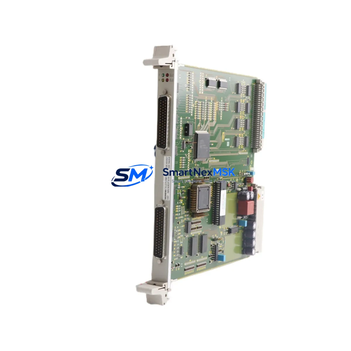
Siemens 6DP1614-8BB Retrofit-Ready Interface for S5 Control Systems
The Siemens 6DP1614-8BB is the IM614 interface module designed for the SIMATIC S5 programmable logic controller platform, operating over the SINEC H1 industrial Ethernet network. As legacy S5 installations approach end-of-support milestones, the 6DP1614-8BB remains a critical retrofit component for engineers who need to extend the operational life of existing control cabinets, migrate communication links, or restore failed network interfaces without a full system replacement. SMARTNEXMSK maintains verified stock of this module, fully tested, with a 12-month warranty and documented outgoing inspection records.
Whether you are replacing a failed IM614 in a running production line, upgrading a distributed I/O network from coaxial SINEC L2 to SINEC H1 Ethernet, or consolidating multiple S5-115U and S5-135U racks onto a single supervisory network, the 6DP1614-8BB provides a direct, wiring-compatible solution that minimises engineering rework and avoids costly reprogramming of existing STEP 5 logic blocks.
Upgrade Compatibility Table
| Parameter | 6DP1614-8BB (IM614) | Retrofit Notes |
|---|---|---|
| Compatible Racks | S5-115U, S5-135U, S5-155U central racks and expansion racks | Verify slot position; IM614 occupies a dedicated interface slot — confirm rack type before ordering |
| Network Protocol | SINEC H1 (Industrial Ethernet, 10 Mbit/s) | Replacing SINEC L2 (token ring) installations requires network topology review and CP module audit |
| Backplane Interface | S5 bus connector, 48-pin edge connector | Confirm backplane bus version; early S5-115U revisions may require bus adapter |
| Power Supply Requirement | 5 VDC via backplane (max 1.2 A); 24 VDC external not required | Audit PS307 or PS951 power supply capacity before adding module to loaded rack |
| Module Address Setting | Hardware DIP switch on module face | Match address to existing STEP 5 DB configuration; document before removal of failed unit |
| Communication Compatibility | SINEC H1 peer-to-peer, S5-compatible FETCH/WRITE services | Verify CP 1430 TF or CP 1434 TF partner modules on remote racks support same service set |
| Replacement Path | Direct drop-in for failed IM614 units; no firmware update required | Cold-swap only; power down rack before insertion |
| Commissioning Requirement | STEP 5 V7.x hardware configuration update recommended | Re-download DB1 / system data block after replacement if address or slot changed |
| Warranty | 12-Month Warranty — all units ship with outgoing functional test report | |
Retrofit Planning for Existing Automation Systems
A successful 6DP1614-8BB retrofit begins well before the module arrives on site. Start by auditing the full rack assembly: identify the central controller — typically a CPU 948 or CPU 928B in an S5-135U chassis — and document every module occupying the backplane, including digital input modules such as the 6ES5 430-4UA12, analog output cards, and any co-processor modules sharing the bus. Record the current power budget drawn from the PS 951 or PS 307 power supply unit; adding or replacing an interface module can shift the 5 V load balance, and an undersized supply is a common cause of intermittent faults after retrofit.
Next, map the SINEC H1 network topology. The 6DP1614-8BB connects to the Ethernet segment via an AUI transceiver or a direct 10BASE-T port depending on the hardware revision. Confirm that the CP 1430 TF communication processor modules installed in partner racks — or any CP 1434 TF units serving as network gateways — are configured with compatible FETCH/WRITE service parameters. If the existing network uses coaxial SINEC H1 cabling, verify that the transceiver and MAU (Medium Attachment Unit) are serviceable; these components are frequently the hidden failure point in aged installations rather than the IM614 itself.
Terminal wiring on the IM614 is limited to the AUI or RJ-45 network port and the backplane edge connector — there are no field-wiring terminals on this module. However, the I/O modules sharing the same rack, such as SM 321 digital input cards or SM 331 analog input modules in mixed S5/S7 migration scenarios, may require terminal block inspection and re-torquing during any planned maintenance window. If the retrofit is part of a broader migration toward SIMATIC S7-300 or S7-400, consider installing an IM 360 / IM 361 expansion interface pair on the new platform in parallel, allowing the S5 rack to remain online during the transition period.
HMI screens connected via SINEC H1 — including legacy OP 17 or OP 27 operator panels configured with S5 FETCH/WRITE drivers — will resume communication automatically once the replacement IM614 is powered and the module address matches the original DIP switch setting. No HMI project download is required provided the module address is preserved. If the address was lost or the original module is unreadable, retrieve the address from the STEP 5 hardware configuration DB or from the network management station if a SINEC NCM configuration file is available.
For sites running SIMATIC NET PC software for network diagnostics, the replacement module will appear on the SINEC H1 segment within seconds of power-up. Use the NCM diagnostic tool to confirm the module MAC address and verify that FETCH/WRITE connections are re-established to all configured partner stations before releasing the line back to production.
Downtime Control During System Migration
Minimising unplanned downtime during an IM614 replacement requires a structured cold-swap procedure. Begin by exporting the complete STEP 5 project from the programming device — a PG 740 or a PC running STEP 5 V7.23 — and archiving the current DB1 system data block, all organisation blocks (OB1, OB13, OB21, OB22), and the hardware configuration. This archive is your recovery baseline if the replacement module requires a fresh hardware configuration download.
Schedule the swap during a planned maintenance window. Power down the rack using the PS 951 main switch, extract the failed IM614 from its slot, and note the DIP switch positions before handling the replacement unit. Insert the 6DP1614-8BB, set the DIP switches to match the documented address, and restore rack power. The CPU should transition to RUN mode within the normal startup sequence; if it halts at STOP, connect the PG and check the diagnostic buffer (DB1 error entries) for address conflicts or bus faults.
If the system cannot tolerate a full rack power-down, consider a parallel-rack strategy: install a second S5-115U rack with a new IM614 and duplicate I/O wiring, bring it online on the SINEC H1 segment, and perform a controlled switchover at the SCADA or DCS level. This approach is particularly effective in continuous-process environments where even a five-minute outage carries significant cost. The 6DP1614-8BB supports this strategy because it is fully compatible with the existing SINEC H1 segment without requiring network reconfiguration on the host side.
After restoration, run a full I/O force test on all digital and analog channels, verify SINEC H1 communication counters in the NCM diagnostic tool, and confirm that the HMI operator panels display correct process values before signing off the maintenance record. All units supplied by SMARTNEXMSK include an outgoing functional test report that can be attached to your maintenance documentation as evidence of pre-shipment verification.
Retrofit Support FAQ
Q1: Is the 6DP1614-8BB a direct replacement for all IM614 variants in the S5 range?
The 6DP1614-8BB is the standard SINEC H1 interface module for the SIMATIC S5 platform. It is compatible with S5-115U, S5-135U, and S5-155U racks that have a dedicated IM slot. Confirm the rack type and slot designation from the original hardware configuration before ordering. Some early S5-115U revisions use a different backplane bus revision — contact our technical team with your rack order number if you are unsure.
Q2: Do I need to update the STEP 5 program after replacing the IM614?
In most cases, no program changes are required if the replacement module is installed in the same slot with the same DIP switch address. A re-download of the hardware configuration (DB1) is recommended as best practice to ensure the CPU recognises the new module serial data. If the slot or address has changed, update the hardware configuration in STEP 5 and re-download before switching to RUN mode.
Q3: What wiring changes are needed when installing the 6DP1614-8BB?
The 6DP1614-8BB connects to the SINEC H1 network via an AUI port (15-pin D-sub) or 10BASE-T RJ-45 depending on hardware revision. No field-wiring terminals are present on the module itself. Ensure the network cable and transceiver are in good condition before installation. The backplane edge connector seats automatically when the module is inserted into the rack slot — no additional wiring is required on the backplane side.
Q4: What does the 12-month warranty cover, and what testing is performed before shipment?
All 6DP1614-8BB units supplied by SMARTNEXMSK undergo a functional test that verifies backplane communication, network port integrity, and DIP switch operation prior to shipment. The 12-month warranty covers manufacturing defects and functional failures under normal operating conditions. Each unit ships with a test report. In the event of a warranty claim, SMARTNEXMSK provides advance replacement to minimise your downtime exposure.
© 2026 SMARTNEXMSK. All rights reserved.
Original Source: https://smartnexmsk.com
Contact: [email protected] | +86 18259474341



