
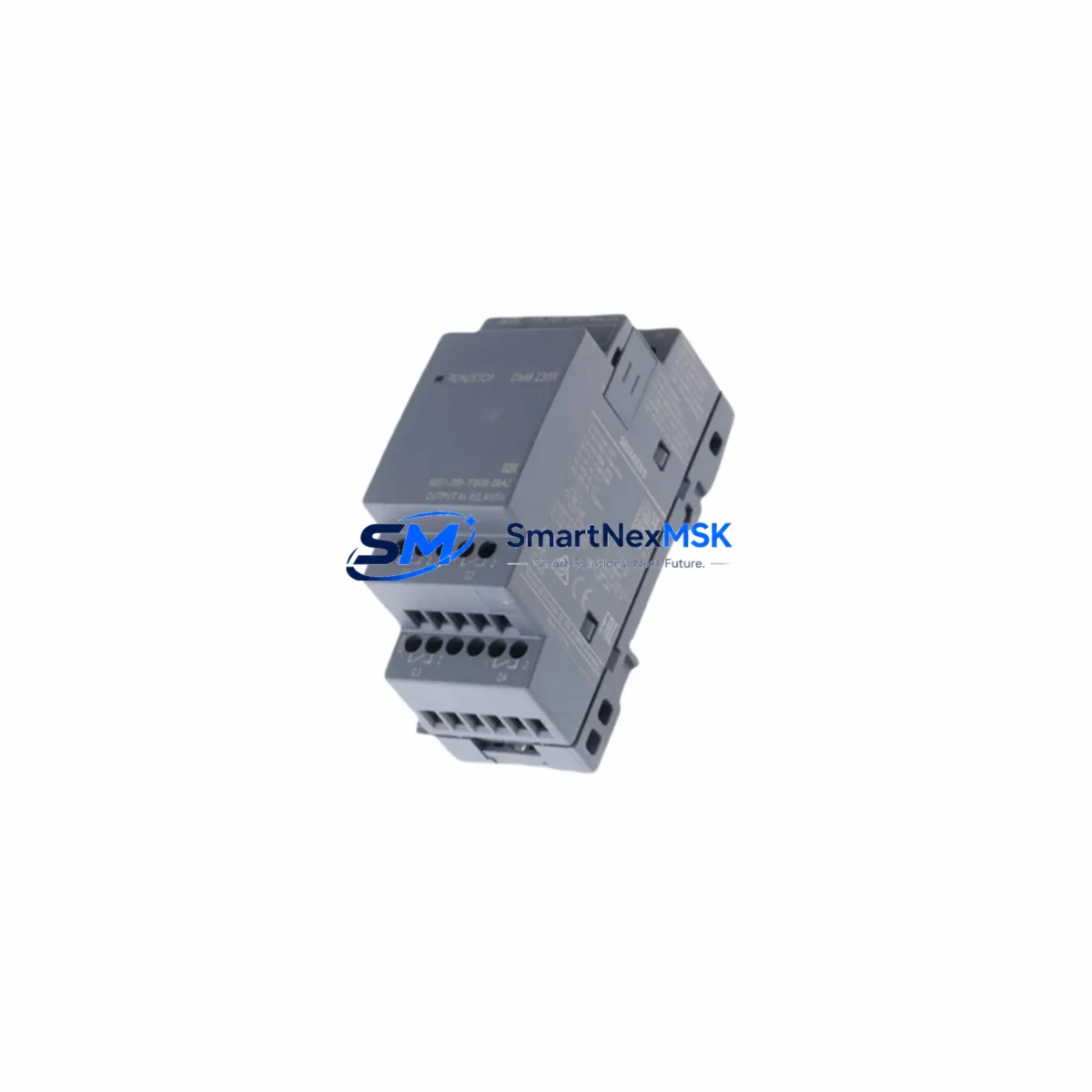
Siemens 6ED1055-1FB00-0BA2 Maintenance-Ready Spare for LOGO! Automation
The Siemens 6ED1055-1FB00-0BA2 is an original LOGO! DM8 24 digital expansion module designed for industrial control systems requiring reliable I/O expansion. With 4 digital inputs and 4 transistor digital outputs rated at 24VDC, this module integrates directly into LOGO! 8 series logic controllers, making it a critical spare part for maintenance engineers managing compact automation panels, machine control cabinets, and building automation systems. Unplanned downtime caused by a failed expansion module can halt production lines, disrupt HVAC sequences, or disable conveyor logic — stocking the 6ED1055-1FB00-0BA2 as a ready spare is a proven strategy for minimizing mean time to repair (MTTR) and sustaining continuous operation.
For maintenance and procurement engineers responsible for aging LOGO!-based systems, this module represents a direct, plug-and-play replacement for worn or failed DM8 units. Its compact DIN-rail form factor, side-bus connector interface, and 24VDC transistor output architecture ensure full backward compatibility with existing LOGO! 8 wiring schemes and program logic — no re-engineering required at the panel level.
Spare Maintenance Table
| Part Number / SKU | 6ED1055-1FB00-0BA2 |
| Brand | Siemens |
| Series | LOGO! (Logic Module) — DM8 24 Expansion |
| Module Type | Digital Expansion Module |
| Digital Inputs | 4 × 24VDC |
| Digital Outputs | 4 × 24VDC Transistor (0.3A per output) |
| Supply Voltage | 24VDC (±20%) |
| Connection Interface | Side-bus connector (LOGO! 8 compatible) |
| Mounting | 35mm DIN Rail |
| Protection Rating | IP20 |
| Operating Temperature | 0°C to +55°C |
| Dimensions (W×H×D) | 36 × 90 × 58 mm |
| Weight | Approx. 230g |
| Country of Origin | Germany |
| Compatibility | LOGO! 8 series base modules (6ED1052-xxx), LOGO! 8.3 series |
| Application Environment | Machine control, building automation, conveyor systems, HVAC panels |
| Maintenance Recommendation | Inspect side-bus connector pins and 24VDC supply integrity at each scheduled PM cycle |
| Warranty | 12 Months — Tested before shipment |
Maintenance Planning for Continuous Operation
When a 6ED1055-1FB00-0BA2 module fails or is flagged during a scheduled inspection, the replacement workflow should extend beyond the module itself. Maintenance engineers should treat this event as a trigger for a broader cabinet audit. The 24VDC bus powering the DM8 module is typically shared with the LOGO! 8 base unit (such as the 6ED1052-1MD08-0BA1 or 6ED1052-1FB08-0BA1), and any voltage sag or ripple on this rail can cause intermittent I/O faults that are misdiagnosed as module failure.
Begin by verifying the 24VDC SITOP power supply module output — units such as the SITOP PSU100S or SITOP compact 24VDC series are commonly paired with LOGO! panels and should be load-tested during the same maintenance window. Check the input wiring terminals on the DM8 for signs of thermal stress, loose ferrules, or corroded contacts on the Phoenix Contact or Weidmüller terminal blocks typically used in these cabinets.
On the output side, inspect the downstream load circuit: if the transistor outputs are driving 24VDC relay coils (such as Siemens 3RH or 3RT series contactors or intermediate relay modules), verify coil resistance and check for welded contacts that may have caused output overcurrent — a common root cause of transistor output degradation. Fuse protection on each output branch should also be confirmed; blade fuse holders or miniature circuit breakers rated at 0.5–1A per channel are standard practice.
If the LOGO! system includes a LOGO! TDE text display (6ED1055-4MH08-0BA1) or a LOGO! CMR2020 communication module for remote monitoring, these should be powered-cycled and communication integrity verified after the DM8 replacement to confirm the side-bus enumeration is correct. For systems using LOGO! Soft Comfort or TIA Portal-integrated LOGO! configurations, re-upload the program and verify I/O mapping before returning the panel to service.
Procurement engineers should maintain a minimum of one 6ED1055-1FB00-0BA2 unit per installed LOGO! panel cluster in the spare parts inventory. For facilities with more than five LOGO! 8 installations, a buffer stock of two to three units is recommended to cover concurrent failures during peak production periods.
Site Replacement Workflow
Step 1 — Isolation: De-energize the control cabinet and lock out / tag out (LOTO) the 24VDC supply rail. Confirm zero voltage at the DM8 supply terminals using a calibrated multimeter.
Step 2 — Disconnection: Disconnect the side-bus connector by pressing the release tab and sliding the DM8 module away from the LOGO! base unit. Label all field wiring before removal.
Step 3 — Inspection: Inspect the side-bus connector on both the base module and the removed DM8 for bent pins, oxidation, or debris. Clean with isopropyl alcohol if required.
Step 4 — Installation: Slide the replacement 6ED1055-1FB00-0BA2 onto the DIN rail and engage the side-bus connector until it clicks. Reconnect field wiring per the original terminal labeling.
Step 5 — Verification: Re-energize the 24VDC supply. Confirm the LOGO! base unit recognizes the expansion module (LED status indicator on DM8 should illuminate). Trigger each digital input and verify the corresponding output response in the LOGO! program.
Step 6 — Documentation: Record the replacement in the panel maintenance log, including the date, replaced module serial number, and technician ID. Update the spare parts inventory accordingly.
This workflow applies equally to legacy LOGO! 0BA7 and 0BA8 installations where the 6ED1055-1FB00-0BA2 is used as a direct functional replacement, allowing older systems to remain operational without controller-level upgrades.
Spare Parts Support FAQ
Q1: Is the 6ED1055-1FB00-0BA2 compatible with older LOGO! 0BA7 base modules?
The 6ED1055-1FB00-0BA2 is designed for LOGO! 8 (0BA8) series base modules. While the physical form factor is similar to 0BA7 expansion modules, the side-bus protocol differs. For 0BA7 systems, verify compatibility with the specific base module firmware version before installation. When in doubt, contact our technical team with your base module part number for confirmation.
Q2: What pre-shipment testing is performed on this module?
Each 6ED1055-1FB00-0BA2 unit is functionally tested prior to shipment: supply voltage acceptance, digital input signal response, and transistor output switching are verified. Units are shipped with original packaging where available and include a 12-month warranty covering manufacturing defects and functional failures under normal operating conditions.
Q3: How should this module be stored as a long-term spare?
Store in original anti-static packaging in a dry environment at 15–35°C with relative humidity below 75% (non-condensing). Avoid proximity to strong magnetic fields or high-vibration areas. Inspect connector pins annually if stored for more than 12 months. Shelf life under proper storage conditions exceeds 5 years.
Q4: Can you supply multiple units for a planned maintenance shutdown or system-wide replacement project?
Yes. We maintain stock of the 6ED1055-1FB00-0BA2 for both single-unit emergency orders and bulk procurement for planned shutdowns. Lead time for standard orders is 1–3 business days. For project quantities of 10 units or more, contact us directly for pricing and delivery scheduling.
© 2026 SMARTNEXMSK. All rights reserved.
Original Source: https://smartnexmsk.com
Contact: [email protected] | +86 18259474341



