
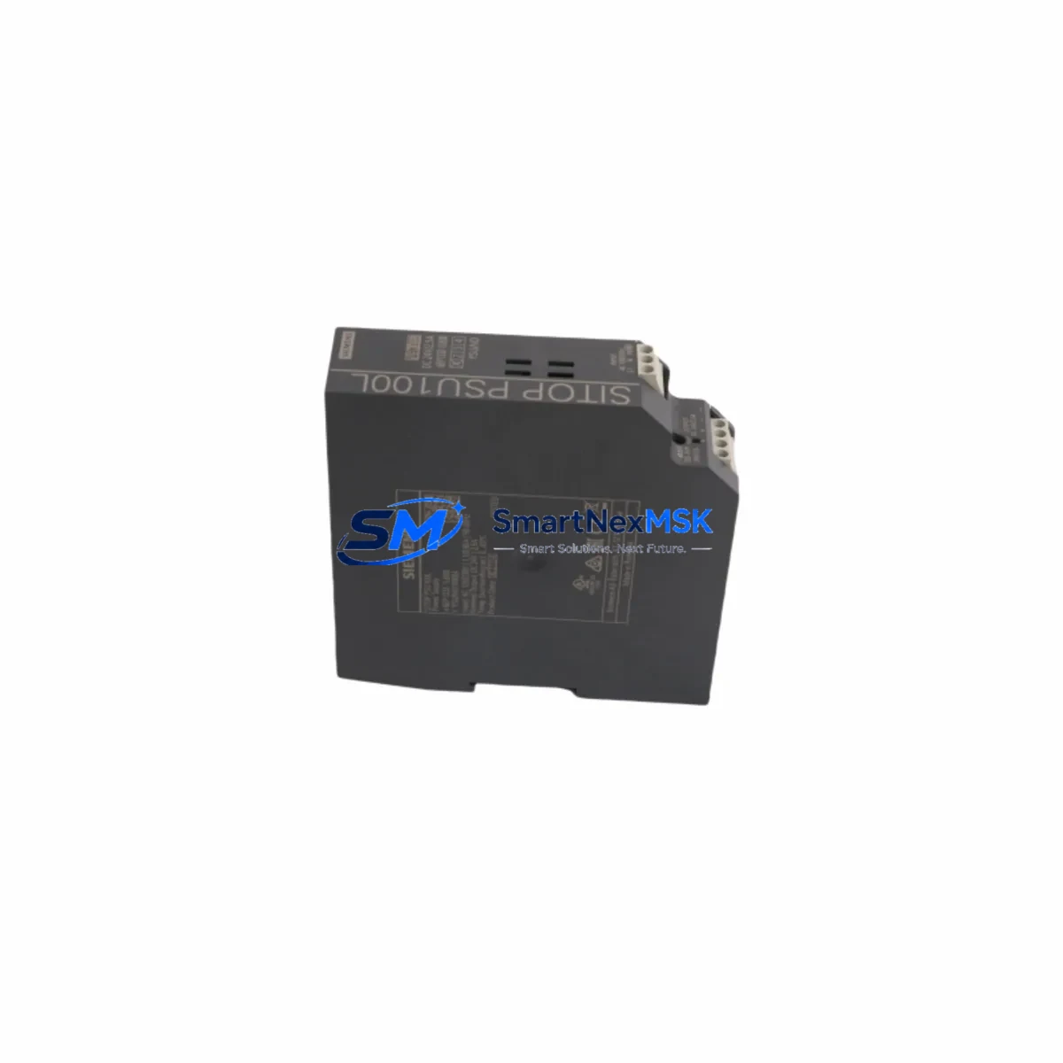
Siemens 6EP1332-1LB00 Maintenance-Ready Spare for SITOP PSU100S Automation
The Siemens 6EP1332-1LB00 is a SITOP PSU100S series single-phase DIN rail power supply delivering a stable 24 V DC / 5 A output for industrial automation systems. As a maintenance-ready original spare, it is engineered to replace aging or failed power supply units in Siemens S7-300, S7-1200, and compatible third-party control cabinets with zero configuration changes. For maintenance engineers managing aging automation infrastructure, having a verified, factory-tested 6EP1332-1LB00 on the shelf is the single most effective measure against unplanned downtime caused by power rail failure.
Industrial power supplies are among the highest-wear components in a control cabinet. Capacitor degradation, thermal cycling, and input voltage fluctuations all accelerate aging. The 6EP1332-1LB00 is designed for continuous duty in harsh environments — wide-range AC input (85–264 V AC), active power factor correction, and integrated output voltage monitoring make it a reliable backbone for PLC racks, distributed I/O nodes, and field device loops. When this unit is scheduled for replacement during planned maintenance or emergency recovery, the surrounding electrical circuit should be systematically inspected to ensure the root cause of failure is addressed and the new unit is protected.
Spare Maintenance Table
| Parameter | Specification |
|---|---|
| Part Number / SKU | 6EP1332-1LB00 |
| Series | SITOP PSU100S |
| Brand | Siemens |
| Output Voltage | 24 V DC (adjustable 24–28 V) |
| Output Current | 5 A continuous |
| Input Voltage | 85–264 V AC, 1-phase, 47–63 Hz |
| Input Power | approx. 150 W |
| Efficiency | ≥ 89% |
| Mounting | DIN rail (35 mm), vertical or horizontal |
| Dimensions (W×H×D) | 45 × 125 × 117 mm |
| Weight | approx. 700 g |
| Protection Class | IP20 |
| Operating Temperature | -25 °C to +70 °C |
| Certifications | CE, UL, cUL, GL, ATEX Zone 2 |
| Origin | Germany |
| Compatibility | Siemens S7-300, S7-1200, ET 200, third-party 24 V DC loads |
| Replacement For | 6EP1332-1LB00 (direct), legacy SITOP SMART 5A units |
| Warranty | 12 Months — tested before shipment |
Maintenance Planning for Continuous Operation
When replacing the 6EP1332-1LB00 in a live control cabinet, a disciplined inspection of the surrounding power distribution and signal chain is essential. A failed or degraded power supply rarely operates in isolation — upstream and downstream components are often stressed or damaged by the same event.
Upstream power path: Begin by inspecting the input fuse or miniature circuit breaker feeding the PSU. A blown fuse or tripped MCB is frequently the first indicator of an overload or short-circuit event that also damaged the power supply. Replace the fuse with the correct rating (typically 6–10 A slow-blow for a 5 A PSU) and verify the incoming AC voltage is within the 85–264 V AC tolerance before energizing the new unit.
24 V DC distribution rail: After confirming the PSU output, check the 24 V DC terminal block distribution rail and any downstream fuse terminal blocks (such as Siemens 3NJ6 or Phoenix Contact PTFIX series) that segment the 24 V bus into protected branches. A shorted field device on one branch can cause repeated PSU shutdowns if the branch fuse is not correctly rated or has failed open.
PLC rack power integrity: For S7-300 systems, the PS 307 power supply module or the CPU’s internal 24 V sensor supply should be verified independently. If the 6EP1332-1LB00 feeds the backplane or I/O rack, inspect the SM 321/SM 322 digital I/O modules for signs of overvoltage damage — particularly output modules with transistor outputs, which are sensitive to voltage spikes during PSU switching events.
Communication and signal integrity: Unstable 24 V supply is a leading cause of intermittent PROFIBUS DP or PROFINET communication faults. After PSU replacement, verify bus termination resistors are intact and that DP/PN communication modules (e.g., CP 342-5, CP 343-1) are re-initializing correctly. Signal isolators and 4–20 mA loop isolators in the same cabinet should also be checked, as they are sensitive to supply ripple.
Relay and contactor coils: Intermediate 24 V DC relay modules (such as Siemens 3RQ or Phoenix Contact PLC-RSC series) share the same 24 V bus. Inspect coil resistance and contact condition — a relay with a shorted coil can draw enough current to trigger PSU overcurrent protection. Similarly, solenoid valve coils wired directly to the 24 V rail should be checked for insulation breakdown.
HMI and operator panel supply: If the same PSU feeds an HMI panel (e.g., Siemens KTP700 Basic or TP1200 Comfort), verify the panel boots correctly and that the supply voltage at the HMI terminals is within the 20.4–28.8 V DC tolerance. Undervoltage at the HMI is a common symptom of a failing PSU that is not yet fully dead but is no longer regulating correctly.
Maintaining a spare 6EP1332-1LB00 alongside a spare 24 V/10 A SITOP PSU100S (6EP1333-3BA00) for higher-load cabinets, a set of rated fuse terminal blocks, and a spare CP communication module ensures that a complete power-related failure can be resolved within a single maintenance shift without waiting for procurement.
Site Replacement Workflow
Step 1 — Isolation and safety: De-energize the cabinet following LOTO procedures. Confirm zero voltage on the AC input terminals and the 24 V DC output bus before removing the failed unit.
Step 2 — Documentation: Photograph the existing wiring, terminal assignments, and DIN rail position before removal. The 6EP1332-1LB00 uses screw-type terminals; note the torque specification (0.8 N·m) for reconnection.
Step 3 — Physical replacement: Unclip the failed unit from the DIN rail, transfer all wiring to the new 6EP1332-1LB00 terminal-by-terminal, and snap the unit onto the rail. Verify the output voltage adjustment potentiometer is set to 24 V before energizing.
Step 4 — Commissioning check: Apply AC power and measure the DC output voltage at the PSU terminals and at the load end of the distribution rail. Acceptable range is 24.0–28.0 V DC. Confirm the green DC OK LED is illuminated and stable.
Step 5 — System restart: Power up the PLC rack, verify CPU goes to RUN mode, confirm all I/O modules report correctly in the hardware configuration, and check that PROFIBUS/PROFINET communication is re-established. Log the replacement in the maintenance record with date, technician, and new unit serial number.
This workflow is compatible with direct replacement of legacy SITOP SMART 5A units and older 6EP1332-1SH31 variants, maintaining full system compatibility without PLC program changes or hardware reconfiguration.
Spare Parts Support FAQ
Q1: Is the 6EP1332-1LB00 a direct drop-in replacement for older SITOP 5A power supplies?
Yes. The 6EP1332-1LB00 (SITOP PSU100S 5A) is dimensionally and electrically compatible with the earlier 6EP1332-1SH31 (SITOP SMART 5A) and fits the same DIN rail footprint. No wiring changes are required. Verify the output voltage setting after installation.
Q2: What pre-shipment testing is performed on this unit?
Each 6EP1332-1LB00 is bench-tested under load before dispatch. Output voltage regulation, overcurrent protection trip point, and DC OK signal function are verified. A test report is available on request. All units carry a 12-month warranty from the date of shipment.
Q3: How should this spare be stored in a maintenance inventory?
Store in original anti-static packaging in a dry environment at 0–40 °C, away from direct sunlight and corrosive atmospheres. Electrolytic capacitors in stored PSUs should be re-formed by applying rated voltage for 30 minutes annually if the unit has been in storage for more than 12 months. Label with receipt date and storage location in your spare parts management system.
Q4: Can this unit be used in ATEX Zone 2 classified areas?
The 6EP1332-1LB00 carries ATEX Zone 2 certification (II 3 G Ex nA IIC T4 Gc) when installed in a suitable enclosure with appropriate cable entry sealing. Confirm the full installation complies with IEC 60079-15 and local hazardous area regulations before commissioning in classified locations.
© 2026 SMARTNEXMSK. All rights reserved.
Original Source: https://smartnexmsk.com
Contact: [email protected] | +86 18259474341



