
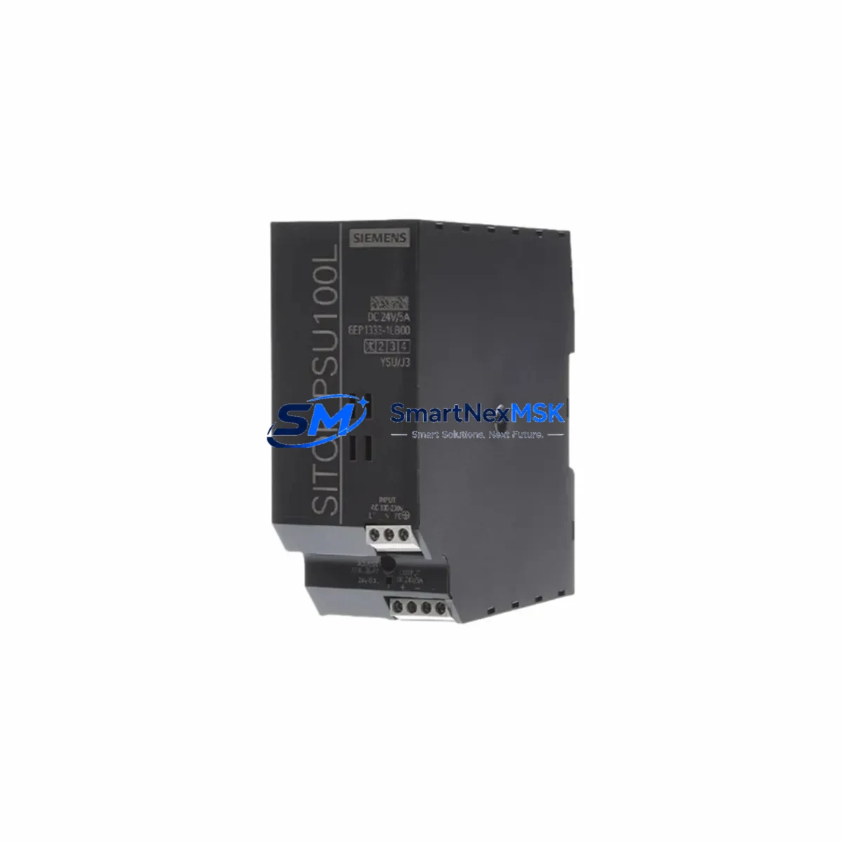
Siemens 6EP1333-1LB00 Retrofit-Ready Power Supply for SITOP Smart Control Systems
The Siemens 6EP1333-1LB00 is a 24 VDC / 5 A regulated power supply from the SITOP Smart series, engineered for continuous-duty industrial control applications. As legacy SITOP Smart units approach end-of-service life or become unavailable through standard distribution channels, the 6EP1333-1LB00 remains one of the most sought-after retrofit and replacement components for control cabinets running SIMATIC S7-300, S7-400, and equivalent automation platforms. Its compact DIN-rail footprint, wide AC input range (85–264 VAC), and robust short-circuit protection make it a direct drop-in candidate for modernization projects where minimizing panel re-engineering is a priority.
Upgrade Compatibility Table
| Parameter | 6EP1333-1LB00 (This Unit) | Retrofit Notes |
|---|---|---|
| Output Voltage | 24 VDC regulated | Matches standard PLC backplane and I/O bus voltage; no step-down required |
| Output Current | 5 A continuous | Verify total load of connected SM modules, CP modules, and field devices before replacement |
| AC Input Range | 85–264 VAC, 47–63 Hz | Universal input; compatible with both 110 VAC and 230 VAC supply circuits without jumper change |
| Mounting | 35 mm DIN rail (EN 60715) | Direct replacement for existing SITOP Smart rail position; no bracket modification needed |
| Terminal Wiring | Screw terminals, 0.5–4 mm² | Retain existing wire ferrules; re-torque to 0.5–0.6 Nm per Siemens wiring spec |
| Communication Compatibility | Passive (no bus interface) | No PROFIBUS or PROFINET address assignment required; transparent to S7 CPU configuration |
| Replacement Scope | Direct swap for 6EP1333-1LB00 and functionally equivalent SITOP Smart 5A variants | Confirm output derating if ambient temperature exceeds 55 °C |
| Commissioning Focus | Output voltage trim, load test, protective earth continuity | Measure 24 VDC at PLC CPU terminal block before restoring control power |
| Warranty | 12-Month Warranty — covers manufacturing defects; includes pre-shipment functional test report | |
Retrofit Planning for Existing Automation Systems
Replacing the 6EP1333-1LB00 in an operating control cabinet requires a structured approach to avoid unplanned downtime and protect the integrity of the existing control program. Begin by auditing the total 24 VDC load in the panel: sum the current draw of all connected SIMATIC SM 321 digital input modules, SM 322 digital output modules, SM 331 analog input modules, and any CP 343-1 or CP 341 communication processors mounted on the S7-300 rack. If the aggregate load approaches or exceeds 4.5 A, consider whether a higher-capacity SITOP PSU8200 10 A unit would provide better headroom for future I/O expansion.
Before de-energizing the cabinet, document the terminal assignment on the existing power supply — L+, M, PE, and any parallel output connections feeding remote I/O drops or distributed ET 200S stations. Photograph the wiring layout and label each conductor. When the 6EP1333-1LB00 is installed, reconnect in the same sequence and verify that the PE (protective earth) conductor is bonded to the DIN rail ground bus before applying AC input power.
For systems using a SIMATIC S7-300 CPU 315-2 DP or CPU 317-2 PN/DP, confirm that the CPU’s power-up sequence is not disrupted by the supply changeover. If the rack also houses a PS 307 5A power supply module in slot 1, note that the 6EP1333-1LB00 is an external panel-mount unit and does not occupy a rack slot — both can coexist to provide redundant 24 VDC rails for critical field circuits. In cabinets where a SITOP UPS1600 uninterruptible power supply module is installed downstream, verify that the UPS input voltage tolerance (21.6–28.8 VDC) is satisfied by the replacement unit’s output trim setting.
For older lines migrating from relay-logic panels to PLC-based control, the 6EP1333-1LB00 is frequently paired with SIMATIC S7-1200 CPU 1214C or CPU 1215C controllers during brownfield upgrades. In these projects, the existing 24 VDC wiring infrastructure is often reused, making the SITOP Smart 5A an economical bridge between legacy field wiring and modern IEC 61131-3 program logic. Ensure that any IM 360/361 interface modules or IM 153-2 distributed I/O adapters on the same 24 VDC bus are within the current budget of the replacement supply.
Downtime Control During System Migration
Minimizing production interruption during a power supply swap on a live automation line requires preparation that begins well before the scheduled maintenance window. First, export and archive the current S7 project from STEP 7 or TIA Portal to a secure offline backup — this protects the CPU program, hardware configuration, and HMI screen data in the event of an unexpected CPU memory loss during power cycling. If the system uses a SIMATIC HMI TP700 Comfort or OP 177B panel, back up the HMI project separately and confirm that the panel’s recipe data and alarm history are stored on an SD card or network share.
Schedule the replacement during a planned production break or shift changeover. Isolate the AC input to the 6EP1333-1LB00 using the cabinet’s main circuit breaker or a dedicated MCB — do not rely solely on the power supply’s internal switch. After installing the replacement unit, perform a no-load voltage check (target: 24.0–24.5 VDC) before reconnecting the PLC rack. Restore power to the CPU first, confirm that the STOP/RUN LED transitions correctly, then re-enable field output modules one group at a time to avoid inrush current spikes that could trigger the supply’s overload protection.
For systems with PROFIBUS DP networks, verify that all DP slave addresses are recognized by the CPU after restart — a missing slave will generate a diagnostic interrupt that may prevent the CPU from entering RUN mode. For PROFINET-based architectures, check the device name assignments in TIA Portal’s online device view before declaring the migration complete. Total planned downtime for a straightforward 6EP1333-1LB00 swap in a well-documented cabinet is typically 30–90 minutes; complex multi-rack systems with distributed I/O may require a 4-hour window.
Retrofit Support FAQ
Q1: Is the 6EP1333-1LB00 a direct replacement for other SITOP Smart 5A variants?
Yes. The 6EP1333-1LB00 is functionally interchangeable with earlier SITOP Smart 5A models sharing the same output rating (24 VDC / 5 A) and DIN-rail form factor. Always verify the output voltage trim and terminal layout against your existing wiring diagram before energizing.
Q2: What commissioning checks are required after installation?
Measure output voltage at the supply terminals (target: 24.0–24.5 VDC under no load, 23.8–24.5 VDC under full load). Verify PE continuity with a milliohm meter. Confirm that the PLC CPU enters RUN mode and that all I/O modules report healthy status in the diagnostic buffer. For PROFIBUS systems, check that all DP slave stations are online.
Q3: Can this unit be used alongside a SITOP UPS module for battery-backed 24 VDC?
Yes. The 6EP1333-1LB00 is compatible as a primary charging source for SITOP UPS modules (e.g., SITOP UPS1600) when the output voltage is within the UPS input range. Confirm the UPS input voltage specification and set the supply output trim accordingly.
Q4: What does the 12-month warranty cover, and is a test report included?
The 12-month warranty covers manufacturing defects and functional failures under normal operating conditions. Each unit ships with a pre-shipment functional test report confirming output voltage, current capacity, and protective circuit operation. Warranty claims are processed via [email protected] with proof of purchase and a fault description.
© 2026 SMARTNEXMSK. All rights reserved.
Original Source: https://smartnexmsk.com
Contact: [email protected] | +86 18259474341



