
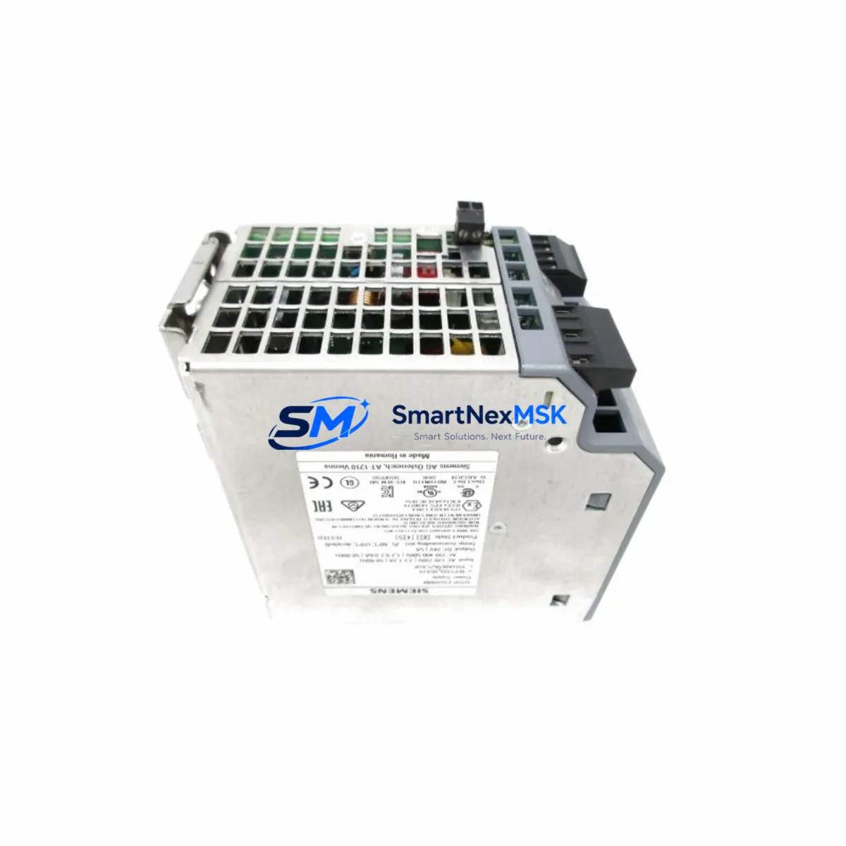
Siemens 6EP1333-3BA10 Maintenance-Ready Spare for SITOP Automation
The Siemens 6EP1333-3BA10 is a SITOP PSU200M series 24 VDC / 5 A single-phase DIN-rail power supply module designed for continuous duty in industrial automation environments. As a maintenance-ready spare, it is the direct replacement for aging or failed units in Siemens S7-300, S7-400, and SINUMERIK control cabinets, enabling rapid restoration of 24 VDC bus power without re-engineering the panel layout or modifying existing wiring harnesses.
For maintenance engineers managing aging Siemens automation lines, unplanned power supply failure is one of the highest-risk single points of failure in a control cabinet. The 6EP1333-3BA10 delivers regulated 24 VDC output with active power factor correction, wide-range AC input (85–264 VAC), and integrated diagnostics signaling — making it a drop-in replacement that restores system operation within minutes of arrival on site. Every unit shipped from our inventory undergoes pre-dispatch functional testing and is backed by a 12-month warranty, giving procurement engineers confidence in both delivery lead time and post-installation reliability.
Whether you are executing a planned annual shutdown, responding to an emergency line stop, or building a strategic spare parts buffer for a multi-line facility, the 6EP1333-3BA10 is a high-priority stocking item. Its compact 45 mm DIN-rail footprint and standard terminal block wiring mean that even a junior technician can complete the swap in under 30 minutes with no special tooling.
Spare Maintenance Table
| Parameter | Specification |
|---|---|
| Part Number / SKU | 6EP1333-3BA10 |
| Series | SITOP PSU200M |
| Brand | Siemens |
| Output Voltage | 24 VDC (adjustable 22.8–26.4 V) |
| Output Current | 5 A continuous |
| Input Voltage | 85–264 VAC, 1-phase, 47–63 Hz |
| Input Power | ≈ 145 W max |
| Efficiency | ≥ 91% at full load |
| Mounting | 35 mm DIN rail (EN 60715) |
| Width | 45 mm |
| Protection Class | IP20 |
| Operating Temperature | -25 °C to +70 °C |
| Diagnostics | DC OK LED + floating relay contact |
| Compatibility | Siemens S7-300, S7-400, SINUMERIK 840D/828D, ET 200 distributed I/O |
| Origin | Germany |
| Certifications | CE, UL, cUL, GL, ATEX Zone 2 |
| Warranty | 12 Months — Tested before dispatch |
| Condition | Original spare, new or refurbished-to-spec |
Maintenance Planning for Continuous Operation
When a 6EP1333-3BA10 fails or is flagged during a routine control cabinet inspection, experienced maintenance engineers know that the power supply is rarely the only component that warrants attention. A systematic inspection of the surrounding electrical circuit significantly reduces the risk of repeat failures and unplanned downtime.
Begin by verifying the upstream AC supply: check the circuit breaker or miniature circuit breaker (MCB) feeding the PSU input terminals, and inspect the surge protection device (SPD) on the incoming AC rail. A degraded SPD is a common silent contributor to premature power supply failure in industrial environments with high transient activity.
On the 24 VDC output side, inspect the Siemens SITOP UPS1600 or equivalent DC UPS buffer module if one is installed in the cabinet — a failing buffer capacitor bank can cause the PSU to operate in a continuous overload condition. Check the 24 VDC distribution terminal blocks (such as Weidmüller or Phoenix Contact feed-through terminals) for signs of thermal discoloration or loose connections, which indicate sustained overcurrent events.
For the S7-300 or S7-400 rack powered by this supply, inspect the CPU module power connector and the PS 307 or PS 405 rack power supply if a secondary supply is present. Verify that the SM 321/SM 322 digital I/O modules and any SM 331/SM 332 analog I/O modules are drawing within their rated current budgets — an overloaded I/O bus is a frequent root cause of PSU thermal stress.
If the cabinet includes a Siemens CP 343-1 or CP 443-1 Ethernet communication processor, confirm that its 24 VDC supply branch is separately fused and that the module’s status LEDs indicate normal operation after PSU replacement. Similarly, check any IM 360/IM 361 expansion rack interface modules for proper backplane power distribution.
For SINUMERIK 840D sl or 828D installations, the 6EP1333-3BA10 often supplies the NCU (Numerical Control Unit) auxiliary 24 VDC rail. After replacement, verify the SINAMICS S120 drive system 24 VDC logic supply and inspect the SMC (Sensor Module Cabinet-Mounted) units for encoder supply continuity. A Siemens SITOP PSA100S selective current limiting module, if installed, should also be tested to confirm its output channels are within tolerance.
Finally, update your spare parts register to include at least one 6EP1333-3BA10 per production line as a minimum stocking level, alongside a spare SITOP PSU100S 24V/10A (6EP1334-2BA20) for higher-current applications in the same cabinet family, ensuring your team can respond to any PSU failure scenario without waiting on procurement lead times.
Site Replacement Workflow
Step 1 — Isolation: De-energize the cabinet via the main isolator. Lock out / tag out (LOTO) per site safety procedure. Confirm 0 V on the PSU input terminals with a calibrated multimeter.
Step 2 — Documentation: Photograph the existing wiring layout, terminal labels, and DIN rail position before removal. Note the output voltage trim potentiometer setting if the unit has been adjusted from factory default.
Step 3 — Removal: Disconnect AC input terminals (L, N, PE) and DC output terminals (+24V, 0V, DC OK relay). Release the DIN rail locking tab and slide the unit off the rail.
Step 4 — Installation: Clip the 6EP1333-3BA10 onto the DIN rail. Reconnect terminals in reverse order — PE first, then L/N, then DC output. Torque terminal screws to 0.5–0.6 Nm.
Step 5 — Commissioning: Re-energize and verify DC OK LED illuminates green. Measure output voltage at the load terminals — adjust trim pot if required to match the previous setting. Confirm PLC CPU and I/O modules return to RUN state without fault codes.
Step 6 — Documentation close-out: Record the replacement in the maintenance log with date, technician ID, and new unit serial number. Update the spare parts inventory to trigger reorder of the consumed spare.
This workflow is compatible with direct replacement of the earlier 6EP1333-1SL11 (SITOP modular 5A) and the 6EP1333-2BA01 (SITOP smart 5A), both of which share the same DIN rail footprint and terminal layout, allowing seamless migration without panel modification.
Spare Parts Support FAQ
Q1: Is the 6EP1333-3BA10 a direct drop-in replacement for older SITOP 5A models?
Yes. The PSU200M series maintains dimensional and terminal compatibility with the SITOP modular and SITOP smart 5A predecessors. No wiring changes or bracket modifications are required for standard DIN rail installations in S7-300 and S7-400 cabinets.
Q2: How is each unit tested before shipment?
Every 6EP1333-3BA10 in our inventory is powered up and load-tested at rated output (24 VDC / 5 A) prior to dispatch. Output voltage, ripple, and DC OK relay function are verified. A test record is retained for traceability. Units that do not meet Siemens factory specification are quarantined and not shipped.
Q3: What is the recommended stocking strategy for multi-line facilities?
For facilities operating three or more Siemens S7-300 or SINUMERIK lines, we recommend a minimum buffer of two 6EP1333-3BA10 units per site. Given the module’s role as the primary 24 VDC source for CPU and I/O racks, a stockout during an unplanned failure can result in extended downtime. Pairing this spare with a SITOP UPS buffer module further reduces exposure to brief AC supply interruptions.
Q4: What does the 12-month warranty cover?
The 12-month warranty covers manufacturing defects and functional failures under normal operating conditions (within rated voltage, current, and temperature limits). It does not cover damage caused by incorrect installation, overvoltage events, or physical impact. Warranty claims are processed within 5 business days of receipt of the returned unit, with replacement dispatch on the same day of claim approval.
© 2026 SMARTNEXMSK. All rights reserved.
Original Source: https://smartnexmsk.com
Contact: [email protected] | +86 18259474341



