
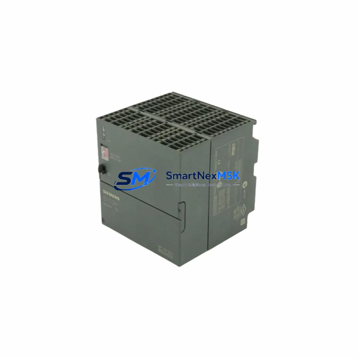
Siemens 6EP1334-1SL12 Maintenance-Ready Spare for SITOP Automation
The Siemens 6EP1334-1SL12 is a SITOP PSU100S series stabilized power supply delivering 24 VDC at 5 A output, designed for continuous-duty industrial automation environments. As a primary 24 VDC rail supplier within control cabinets built around Siemens S7-300, S7-400, and ET 200 distributed I/O systems, this unit is a critical component in the power distribution architecture of countless production lines, process control panels, and machine tool enclosures worldwide. When this power supply fails or approaches end-of-service, the downstream impact is immediate: PLC racks lose logic power, field I/O modules go offline, and operator HMI panels lose communication — bringing production to a halt.
Sourced directly and dispatched from our Xiamen warehouse, each 6EP1334-1SL12 unit undergoes functional testing prior to shipment. Output voltage regulation, current limiting behavior, and input voltage tolerance are verified before packaging. Every unit ships with a 12-month warranty covering manufacturing defects and functional performance under normal operating conditions.
Spare Maintenance Table
| Parameter | Details |
|---|---|
| SKU / Part Number | 6EP1334-1SL12 |
| Brand / Manufacturer | Siemens |
| Product Series | SITOP PSU100S |
| Output Voltage | 24 VDC (regulated) |
| Output Current | 5 A continuous |
| Input Voltage Range | 85–264 VAC / 110–300 VDC (wide-range input) |
| Mounting | DIN rail (35 mm TS 35); standard control cabinet installation |
| Compatibility | Siemens S7-300, S7-400, ET 200M, ET 200S, SIMATIC HMI panels, and 24 VDC field device circuits |
| Protection Features | Overload, short-circuit, and overvoltage protection; active power factor correction |
| Replacement Suitability | Direct spare for failed or end-of-life 6EP1334-1SL12 units; verify terminal block wiring and load current before installation |
| Commissioning Notes | Confirm input fuse rating, output load current, and downstream device power requirements before energizing |
| Warranty | 12 months from date of shipment; covers manufacturing defects and functional performance |
| Origin | Germany |
Maintenance Planning for Continuous Operation
A structured spare parts strategy for control cabinets housing the 6EP1334-1SL12 must account for the full 24 VDC power distribution chain. The power supply does not operate in isolation — it feeds a network of downstream components whose reliability depends directly on stable, regulated DC power. Maintenance engineers planning a cabinet inspection or a scheduled replacement should assess the condition of the entire power rail, not just the supply unit itself.
Begin with the input side. The 6EP1334-1SL12 is typically protected by a miniature circuit breaker or a fuse holder mounted on the same DIN rail section. Inspect the input fuse or MCB for signs of thermal stress or contact degradation. A marginal fuse that has been subjected to repeated inrush events may not trip cleanly under fault conditions, allowing a downstream short circuit to damage the power supply before protection operates.
On the output side, the 24 VDC rail typically feeds a Siemens S7-300 CPU module — such as a 6ES7315-2AH14-0AB0 or similar — along with one or more signal modules mounted in the same rack. SM 321 digital input modules, SM 322 digital output modules, and SM 331 analog input modules all draw from the same 24 VDC bus. If the power supply has been operating in a degraded state — delivering slightly low output voltage or exhibiting intermittent current limiting — these modules may have been subjected to undervoltage stress. During a planned replacement of the 6EP1334-1SL12, it is good practice to measure the actual output voltage at the terminal block under full load before shutdown, and to inspect the module status LEDs for any latent fault indications.
The 24 VDC rail also powers field devices connected through the I/O modules. Proximity sensors, solenoid valve coils, and signal isolators — such as a Phoenix Contact or Weidmüller signal conditioning module — all depend on a stable 24 VDC supply. If the failed power supply caused a voltage dip, field devices may have reset or entered fault states that require manual acknowledgment after the new supply is energized.
In cabinets where the S7-300 rack communicates via PROFIBUS DP, the PROFIBUS network segment connected to a CP 342-5 or CP 343-5 communications processor must be verified after power restoration. A power interruption can cause PROFIBUS slaves — including ET 200M remote I/O stations or Siemens SINAMICS drive units — to drop off the network and require a master reset or a GSD re-initialization before normal communication resumes.
For cabinets equipped with a Siemens SIMATIC HMI panel — such as a KTP700 Basic or TP1200 Comfort — the HMI power input is typically derived from the same 24 VDC rail. After replacing the 6EP1334-1SL12, confirm that the HMI panel restarts cleanly and re-establishes its Ethernet or MPI communication link to the S7-300 CPU. If the HMI project uses alarm archiving or recipe management, verify that the data integrity was maintained through the power interruption.
Terminal blocks and wiring ferrules in the output circuit should also be inspected during the replacement. Loose terminal connections on the 24 VDC output bus are a common cause of intermittent voltage drops that are difficult to diagnose under load. Re-torque all output terminal screws to the manufacturer’s specification and inspect wiring ferrules for signs of corrosion or mechanical damage. If the cabinet uses a Weidmüller or Phoenix Contact terminal block strip for 24 VDC distribution, this is an appropriate time to replace any discolored or heat-stressed terminals.
Site Replacement Workflow
Replacing the 6EP1334-1SL12 in a live production environment requires a disciplined sequence to minimize downtime and protect the integrity of the connected control system. The following workflow is recommended for maintenance engineers performing an unplanned emergency replacement or a scheduled preventive swap.
Before the maintenance window, confirm that the replacement unit has been received, inspected, and verified against the original part number. Check the label on the replacement unit for output voltage and current ratings. Pre-stage the unit at the cabinet location with the correct screwdriver and terminal labeling materials.
At the start of the maintenance window, initiate a controlled shutdown of the PLC program if process conditions allow. Place the S7-300 CPU in STOP mode via the SIMATIC Manager or TIA Portal before removing power. This prevents the CPU from logging spurious I/O errors during the power interruption and avoids unintended output activations when power is restored.
Photograph the existing terminal wiring on the input and output sides of the 6EP1334-1SL12 before disconnection. Label the input live, neutral, and earth conductors, and label the positive and negative output terminals. Disconnect the input supply first, then the output terminals. Remove the unit from the DIN rail by releasing the DIN rail latch.
Install the replacement unit on the DIN rail, reconnect the output terminals first, then the input supply. Apply power and verify the output voltage at the terminal block using a calibrated multimeter before placing the CPU back in RUN mode. Confirm that all downstream modules, field devices, and HMI panels have powered up correctly before resuming production.
All 6EP1334-1SL12 units shipped from our Xiamen facility are tested for output voltage accuracy, current limiting response, and input voltage tolerance before dispatch. This pre-shipment verification supports a faster on-site commissioning process and reduces the risk of a second failure event during the maintenance window.
Spare Parts Support FAQ
Q1: Is the 6EP1334-1SL12 still in production, and can you guarantee long-term supply?
The 6EP1334-1SL12 is a SITOP PSU100S series unit. We maintain stock of both current-production and legacy SITOP power supply variants to support long-term maintenance requirements. Contact our sales team to confirm current stock levels and lead times for your specific quantity requirement.
Q2: What compatibility checks should I perform before installing the replacement unit?
Verify that the input voltage at your cabinet matches the wide-range input specification (85–264 VAC). Confirm that the total 24 VDC load current drawn by all downstream devices does not exceed 5 A. Check that the output terminal block wiring gauge is appropriate for the output current. If the original unit was fitted with an output voltage adjustment, note the setting before removal and replicate it on the replacement unit.
Q3: Does the unit ship with a warranty, and what does it cover?
Yes. Every 6EP1334-1SL12 unit ships with a 12-month warranty from the date of shipment. The warranty covers manufacturing defects and functional performance failures under normal operating conditions. It does not cover damage resulting from incorrect installation, input overvoltage, or environmental contamination beyond the unit’s rated IP20 protection class.
Q4: Can you supply other SITOP or S7-300 components needed for the same cabinet maintenance project?
Yes. We regularly supply SITOP power supply variants across the PSU100S, PSU200M, and SITOP modular ranges, as well as S7-300 CPU modules, signal modules, communications processors, and ET 200 remote I/O components. Provide your full bill of materials and we will advise on availability, lead times, and consolidated shipping options.
© 2026 SMARTNEXMSK. All rights reserved.
Original Source: https://smartnexmsk.com
Contact: [email protected] | +86 18259474341



